
Estimated Study Time: 9 minutes
Generator set(s) connections to LV system
Many different system designs are possible, but for highest reliability, systems are typically configured so that generator set(s) are connected at low voltage, with the minimum number of transformers and circuit breakers between the generator set and load to be served.
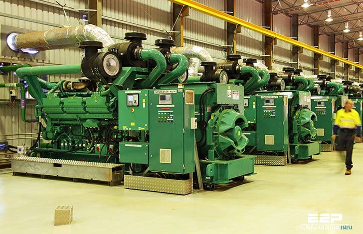 4 typical designs for connecting generator set(s) to the low voltage system (photo credit: Cummins)
Local laws often require that emergency loads are electrically separated from non–emergency loads, and given preference in service so that overloads will result in the non–emergency loads are shed, because this provides the greatest reliability of service to the most critical loads in the system.
Let’s see four most common designs for connecting generator set(s) to the low voltage systems:
- Generator set serving common loads
- Multiple generator sets serving common loads
- Single generator set standby applications
- Multiple generator sets, multiple ATS applications
1. Generator set serving common loads
Generator sets are commonly provided with a main circuit breaker that is mounted on the generator set and service to loads is provided through a separate distribution panel as shown in Figure 1.
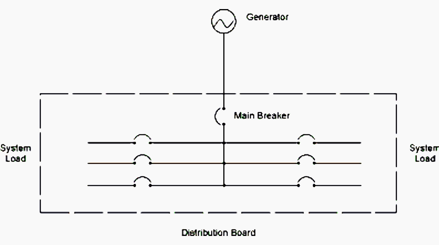
Generators are required to be provided with overcurrent protection, and that can be provided in many forms, which include a breaker mounted in the distribution panel, as shown in Figure 1.
The significance of this is that the protection may be located at the generator set or in a remote panel. If the generator set circuit breaker is omitted, a disconnect switch may still be required by code at the generator set, to provide a point of isolation. Refer to local codes and standards for requirements for generator disconnects or isolation.
Go back to connecting generator set(s) designs ↑
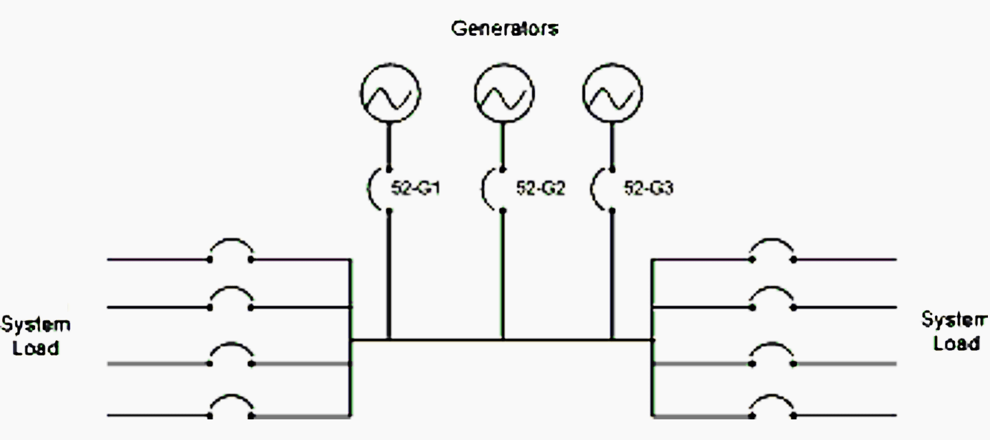
2. Multiple generator sets serving common loads
Figure 2 shows a similar application with paralleling generators replacing the single generator set. In this situation the generator sets may be specifically selected to be of multiple sizes to allow for minimizing the fuel consumption at a site by closely matching the capacity of the operating equipment to the system loads.
Use of dissimilar–sized generator sets may require specific system grounding (earthing) arrangements.
Go back to connecting generator set(s) designs ↑
3. Single generator set standby applications
Figure 3 represents a typical single set power transfer scheme for one utility (mains) supply at low voltage, as may be applied to many domestic, commercial and small industrial applications.
An automatic transfer switch (ATS), which may use contactors, circuit breakers or a dedicate transfer module, is used to transfer the electrical supply to the load from utility to generator.
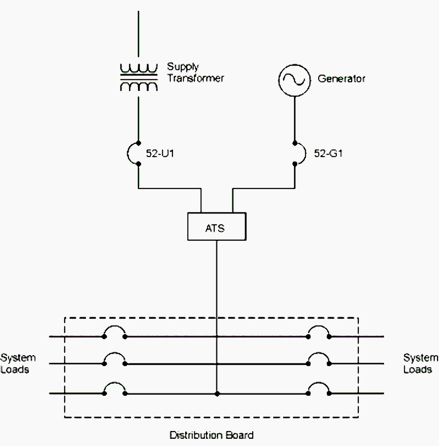
Three–pole generator and utility circuit breakers or fuse–switches are often used to limit the fault level present at the ATS. The ATS may be a 3–pole (solid, non–switched neutral) or 4–pole (switched neutral) device. Typically, 4–pole ATS equipment is used in applications where it is necessary to isolate the supply neutral from the generator neutral.
Power transfer switches and generator sets should not be connected to a utility service prior to this review (and utility approval, if required by local law).
Note that some local codes and standards require the use of multiple transfer switches due to requirements to isolate emergency loads from standby loads.
In these cases, the transfer switches may be located on the load side of the utility distribution panel, and the generator set may also need a distribution panel when the feeder breakers for the ATS equipment cannot be mounted on the generator set.
Go back to connecting generator set(s) designs ↑
4. Multiple generator sets, multiple ATS applications
Larger systems can utilize multiple ATS units and protection located close to the loads. These are often considered to be more reliable than those employing a single large ATS, because faults in the distribution system are more likely to occur toward the load end of a distribution system and the use of multiple switches would result in less of the system being disrupted when a fault occurs.
Figure 4 illustrates a design suited to larger installations, particularly where multiple buildings are served by the same generator installation.
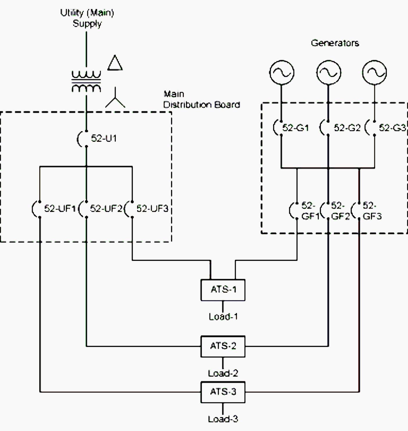
In this system, three ATS units are used, supplied by a common utility and generator system. This scheme can be further adapted to operate from separate utility systems.
This scheme enables a versatile generation system to be constructed and can readily be adapted to multiple sets.
Go back to connecting generator set(s) designs ↑
Cummins generator set 250kVA – Introduction and testing
Load testing a 500kVA generator
A follow-up to my August 2011 generator test video. Every six months (unless we’ve had a power failure in the mean time) we perform a load test of our main standby generator at the office. Rather than hiring a dummy load, we just use the electrical equipment in the office itself, which also gives us a chance to identify any “trigger-happy” breakers within the building.
We don’t perform a full-load test, but a combination of all the lighting, air conditioning and the IT server room gives us around 150kW to play with, almost a 40% load.
500KVA diesel generator set cold start
500KVA Cummins Diesel Generator set cold start/Backfire, been stood for a while and the temperature was -20°C. The controller shut it down after it revved up at the end.
Go back to connecting generator set(s) designs ↑
Reference // Electrical design of the on-site generation system by Cummins Power Generation
Related electrical guides & articles


Edvard Csanyi
Hi, I'm an electrical engineer, programmer and founder of EEP - Electrical Engineering Portal. I worked twelve years at Schneider Electric in the position of technical support for low- and medium-voltage projects and the design of busbar trunking systems.I'm highly specialized in the design of LV/MV switchgear and low-voltage, high-power busbar trunking (<6300A) in substations, commercial buildings and industry facilities. I'm also a professional in AutoCAD programming.
Profile: Edvard Csanyi

Will the three generators connect simultaneously to the bus?
There should be an interlock to ensure that only one is connected, and each generator should be sized for 100% of the load.
hi
am asking about the calculations of short circuit current on the busbar when connecting more than one Generator (for example 6 * 1500 KVA generators connected to the main synchronization busbar
thanks a lot
Subscribed
Hello,
For multiple units (2+) connected to the same busbar, what’s the best solution for preventing current recirculation on the Neutral loops? You mention need of “specific grounding arrangements”, with no further detail…
Thank you, regards
GREAT ARTICLE!
In the case where 2 generators are connected to an ATS. How does NGR get connected in this case?
Would you have 2 separate NGR boxes with their own sensing and tripping equipment?
Thank you.
Our mission is to be the leading provider of scientific information in the field of power and engineering in general. We publish, we share and we spread the knowledge.
You’re welcome to read, write and contribute to EEP in any way!
download link for the reference book please
https://electrical-engineering-portal.com/download-center/books-and-guides/power-substations/electrical-design-of-genset