
Connections of voltage transformers
Voltage transformers would have primaries that are either connected directly to the power system (VTs) or across a section of a capacitor string connected between phase and ground (coupling capacitor voltage transformers – CCVTs).
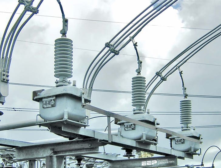 Voltage transformers for protective relay applications (on photo: ARTECHE’s voltage transformers with oil-paper insulation)
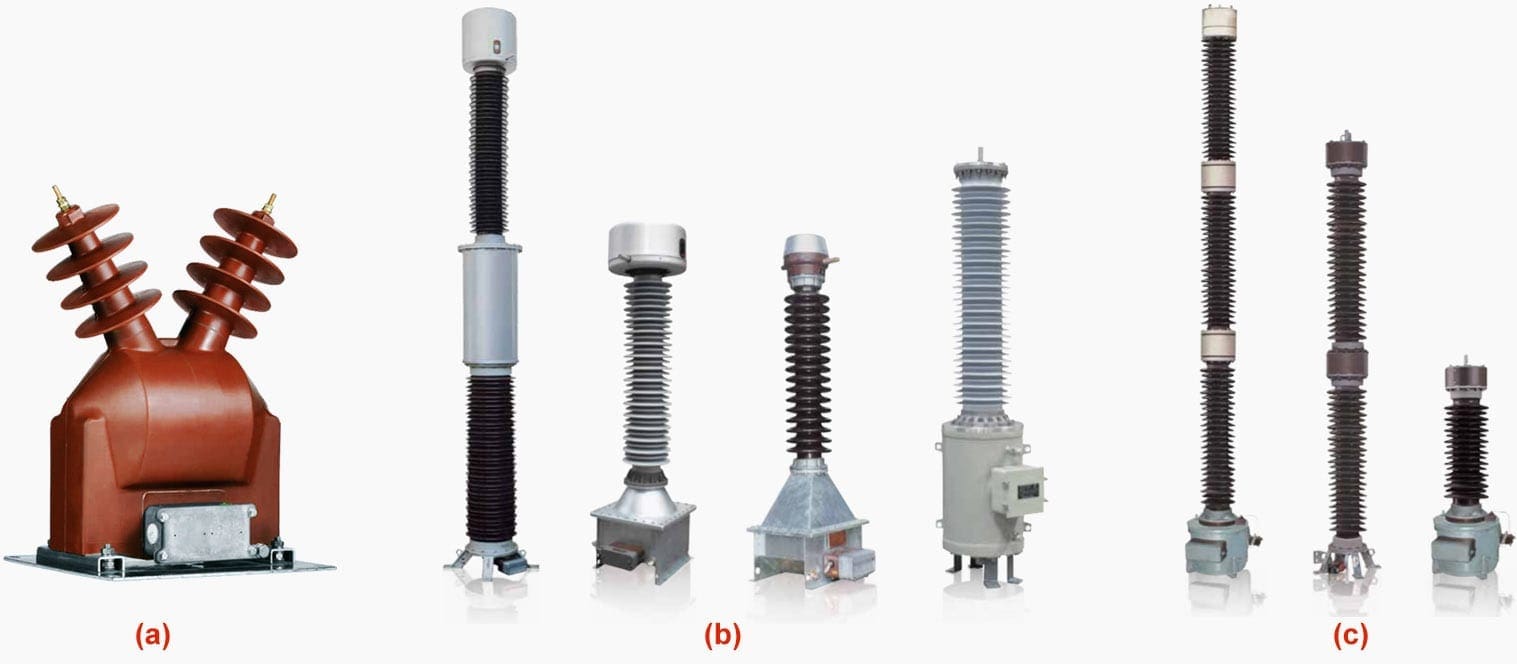
Typical units are illustrated in Figure 1a 1b and 1c:
- Medium voltage transformer up to 36 KV;
- Inductive voltage transformers are designed to provide a scaled down replica of the voltage in the HV line and isolate the measuring instruments, meters, relays, etc., from the high voltage power circuit. For voltages up to 520 KV;
- Capacitive voltage transformers (CVTs) isolate the measuring instruments, meters, relays, protections, etc., from the high voltage power circuit and provide a scaled replica of the voltage in the HV line. They enable transmission of high frequency signals through the high voltage (HV) lines. Coupling capacitors are only used for coupling high frequency communication signals, making them equivalent to the capacitive part of a CVT. For voltages up to 820 KV.
Typical connection schematics are shown in Figure 2:
- Secondary phase-and-ground voltage with three double secondary VTs connected phase-to-ground;
- Secondary phase voltage with two single secondary VTs connected open delta;
- Secondary phase-and-ground voltage with three coupling capacitor voltage transformers (CCVTs) connected phase-to-ground. Only one phase is shown, b and c phases are duplicated with secondaries connected as in (a).
Protective relays utilizing voltage are usually connected phase-to-phase, so the transformers are normally rated 120 V line-to-line. Taps may be provided to obtain either 69.3 V or 120 V line-to-neutral.
When available, double secondaries provide the means of obtaining zero-sequence voltage for ground relays (see Figure 2a).
If only a single transformer secondary winding is available, an auxiliary wye ground-broken delta auxiliary VT can be connected to the secondary a, b, and c bus of Figure 2a for 3V0, similar to the connections shown.
A typical example is shown in Figure 3 below.
Coupling capacitor voltage transformers (CCVTs) commonly have double secondaries for both phase and 3V0 voltages (see Figure 2c). Three VTs or three CCVTs, such as shown in Figure 2a and 2c, pass positive-, negative-, and zero-sequence voltage.
The open-delta connection of Figure 2b will pass both positive-sequence and negative-sequence voltage, but not zero-sequence voltage.
VTs are used at all power system voltages and are usually connected to the bus.
At about 115 kV, the CCVT type becomes applicable and generally more economical than VTs at the higher voltages. Usually, the CCVTs are connected to the line, rather than to the bus, because the coupling capacitor device may also be used as a means of coupling radio frequencies to the line for use in pilot relaying.
Either type of transformer provides excellent reproduction of primary voltage, both transient and steady-state, for protection functions. Saturation is not a problem because power systems should not be operated above normal voltage, and faults result in a collapse or reduction in voltage.
Both have ample capacity and are highly reliable devices. VTs are normally installed with primary fuses that are not necessary with CCVTs. Fuses are also used in the secondary.
Some CCVTs may exhibit a subsidence transient when the system voltage is suddenly reduced, such that the secondary voltage is not a replica of the primary, momentarily. This is caused by the trapped energy ringing in the secondary compensating or turning reaction (L) and the associated circuit.
This transient can be at a different frequency from that of the system frequency, or unidirectional. This has not been a problem for electromechanical relays, but it may cause problems for solid-state types.
Modern-design CCVTs are available to eliminate this problem.
References //
- Protective Relaying Principles and Applications by J. Lewis Blackburn and Thomas J. Domin (Purchase from Amazon)
- Instruments transformers outdoor by Arteche


Thanks alot about this information
Nice Article for new comers & informatic for working professionals in Grid Stations.
Is ferro-resonance a problem at all with Ygnd-Ygnd connection of VTs in the MV applications?
I like your articale. Please share more article to boost the knowledge.