
Estimated Study Time: 13 minutes
Testing Insulation Resistance
The following schemes show how to connect a Megger insulation tester to various types of electrical equipment. The schemes also show in principle how equipment must be disconnected from other circuits before the instrument is connected.
 Connection Schemes For Testing Insulation Resistance Of Electrical Equipment (photo credit: malloyelectric.com)
These illustrations are typical and will serve as guides for testing insulation resistance of practically all types of apparatus and conductors. Before proceeding with tests, read the part on Preparation of apparatus for test at the bottom of this article.
REMEMBER! The Megger insulation resistance tester measures whatever resistance is connected between its terminals. This may include series or parallel leakage paths through insulation or over its surface.
Electrical equipment to test //
- AC Motors and Starting Equipment
- DC Generators and Motors
- Wiring Installation
- Appliances, Meters, Instruments and Other Electrical Apparatus
- Control, Signaling and Communication Cables
- Power Cables
- Power Transformers
- AC Generators
Important //
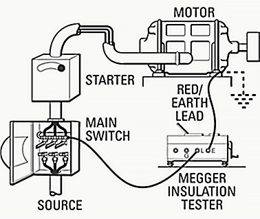
1. AC Motors and Starting Equipment
Connections for testing the insulation resistance of a motor, starting equipment and connecting lines, in parallel. Note that the starter switch is in the “on” position for the test. It is always preferable to disconnect the component parts and test them separately in order to determine where weaknesses exist.
Go back to Equipment To Test ↑
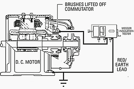
2. DC Generators and Motors
With the brushes raised as indicated, the brush rigging and field coils can be tested separately from the armature. Likewise the armature can be tested by itself. With the brushes lowered, the test will be that of brush rigging, field coils and armature combined.
Go back to Equipment To Test ↑
3. Wiring Installation
Connections for testing to ground each circuit separately, working from the distribution panel.
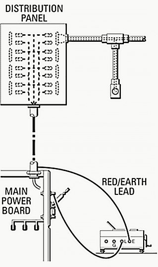
Connections at the main power board, from which point the entire system can be tested to ground at one time, providing all switches in the distribution panel are closed.
Go back to Equipment To Test ↑
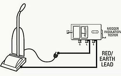
4. Appliances, Meters, Instruments and other electrical apparatus
Connections for testing an appliance. The test is made between the conductor (the heating unit, motor, etc.) and exposed metal parts. The apparatus must be disconnected from any source of power and placed on some insulating material.
Go back to Equipment To Test ↑
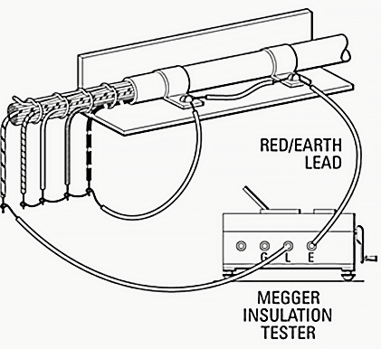
5. Control, Signaling and Communication Cables
Connections for testing insulation resistance of one wire in a multiconductor cable against all other wires and sheath connected together.
Go back to Equipment To Test ↑
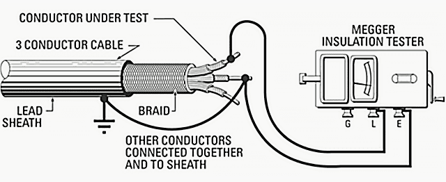
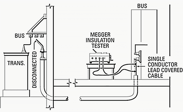
6. Power Cables
Connections for testing the insulation resistance of a power cable. When testing cable, it is usually best to disconnect at both ends in order to test the cable by itself, and to avoid error due to leakage across or through switchboards or panelboards.
Go back to Equipment To Test ↑
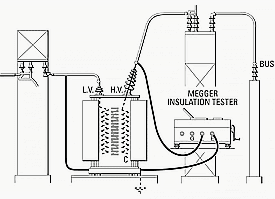
7. Power Transformers
Connections for testing insulation resistance of a transformer high voltage winding and bushings, and the high tension disconnect switch, in parallel, with reference to the low voltage winding and ground. Note that the low voltage winding is grounded for this test.
Go back to Equipment To Test ↑
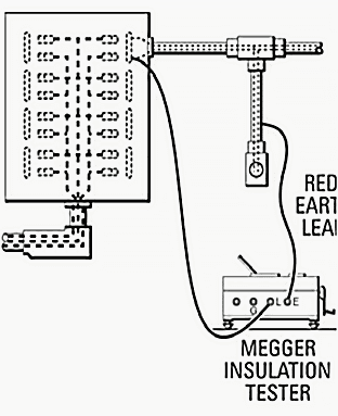
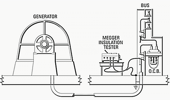
8. AC Generators
With this connection, the insulation resistance will be that of the generator stator winding and connecting cable combined. To test either the stator winding or the cable itself, the cable must be disconnected at the machine.
Preparation of apparatus to test //
1. Take out of Service
- Shut down the apparatus.
- Open switches.
- De-energize.
- Disconnect from other equipment and circuits, including neutral and protective (workmen’s temporary) ground connections.
2. Make Sure Just What is Included in the Test
Inspect the installation very carefully to determine just what equipment is connected and will be included in the test, especially if it is difficult or expensive to disconnect associated apparatus and circuits.
Pay particular attention to conductors that lead away from the installation. This is very important, because the more equipment that is included in a test, the lower the reading will be, and the true insulation resistance of the apparatus in question may be masked by that of the associated equipment.
It is always possible, of course, that the insulation resistance of the complete installation (without disconnecting everything) will be satisfactorily high, especially for a spot check. or, it may be higher than the range of the Megger instrument in use, in which case nothing would be gained by separating the components, because the insulation resistance of each part would be still higher.
For an initial test, it may be necessary to separate the component parts, even though labor and expense are involved, and test each one separately. Also make a test of all the components connected together. With this information on record, it may not be necessary to separate the components on future tests unless unaccountably low readings are observed.
3. Discharge of Capacitance
It is very important that capacitance be discharged, both before and after an insulation resistance test. It should be discharged for a period about four times as long as test voltage was applied in a previous test.
Megger instruments are frequently equipped with discharge circuits for this purpose. If a discharge function is not provided, a discharge stick should be used. Leave high capacitive apparatus (i.e., capacitors, large windings, etc.) short circuited until ready to re-energize.
4. Current leakage at Switches
When apparatus is shut down for the insulation resistance test, make sure that the readings are not affected by leakage over or through switches or fuse blocks, etc. Such leakage may mask the true insulation resistance of the apparatus under test, or, what may be more serious, current from an energized line may leak into the apparatus and cause inconsistent readings, particularly if the live line is DC.
However, such leakage usually can be detected by watching the pointer of the Megger instrument at the moment the test leads are connected to the apparatus and before the instrument is operated.
Before making these observations, be sure that all capacitance is discharged by short circuiting or grounding the apparatus.
Go back to Equipment To Test ↑
Safety precautions //
Observe all rules for safety when taking equipment out of service. Block out disconnect switches. Test for foreign or induced voltages. Apply workmen’s grounds.
Therefore, rather than removing a workmen’s ground in order to make a test, it is more advisable to disconnect the apparatus, such as a transformer or circuit breaker, from the exposed bus or line, leaving the latter grounded. Use rubber gloves when connecting the test leads to the apparatus and while operating the Megger instrument.
Apparatus Under Test Must Not Be Live!
If neutral or other ground connections have to be disconnected, make sure they are not carrying current at the time, and that when disconnected no other equipment will lack necessary protection.
Pay particular attention to conductors that lead away from the circuit being tested and make sure they have been properly disconnected from any source of voltage.
Shock Hazard from Test Voltage
Observe the voltage rating of the Megger instrument and regard it with appropriate caution. Large electrical equipment and cables usually have sufficient capacitance to store up a dangerous amount of energy from the test current. Make sure this capacitance is discharged after the test and before handling the test leads.
Explosion and Fire Hazard
So far as is known, there is no fire hazard in the normal use of a Megger or any other insulation tester. There is, however, a hazard when testing equipment located in inflammable or explosive atmospheres.
Go back to Equipment To Test ↑
Video Tutorials
A tutorial on insulation testing. I cover the different test methods, an analogy on how insulation testing works, safety and the use of insulation test equipment. In this video:
- What is insulation testing / what is megger testing / what is PAT (Portable Appliance Testing) testing?
- Electrical safety when working in a DB board / breaker box or around high energy circuits.
- Insulation test types: Proof test, Spot test, Time Resistance testing, Step Level Voltage test, Polarization Index (PI) test, Dielectric Absorption Ratio (DAR) test.
- Leakage currents: conductive leakage current, capacitive charging leakage current and polarization absorption leakage current in a dielectric.
- Fluke 1587 Insulation Meter
Insulation Resistance Testing / Megger Testing (1)
Insulation Resistance Testing / Megger Testing (2)
Go back to Equipment To Test ↑
Reference // ‘A Stitch In Time’ – The Complete Guide to Electrical Insulation Testing // by MEGGER
Related electrical guides & articles


Edvard Csanyi
Hi, I'm an electrical engineer, programmer and founder of EEP - Electrical Engineering Portal. I worked twelve years at Schneider Electric in the position of technical support for low- and medium-voltage projects and the design of busbar trunking systems.I'm highly specialized in the design of LV/MV switchgear and low-voltage, high-power busbar trunking (<6300A) in substations, commercial buildings and industry facilities. I'm also a professional in AutoCAD programming.
Profile: Edvard Csanyi

Dear Sir,
We have a system which the Voltage Surface is 220KV and itis running System.
Can we perform the IR test of 220KV CB by using 5KV Insulation tester?
We are thinking the system is normal running in 220KV is it logical to do the IR test?
Thanks and Regards
Very important for electrótecnica job!!
Its really great.. I learned the safety procedure and proper approach in doing this insulation testing and easy to understand with the illustrations.. Thank you very much.
Hi, I liked your article very much, and I’m sharing this on a FB group ‘MeteringCurry’ ( on.fb.me/1ZvG4Rx ) Hope it’s ok with you…
Hi
Am electrical trainee..I have just bought my a fluke insulation tester 1507. I want to test 380vac motors.
What happened is..I set the tester at 1000vdc..then I connect the common to the motor frame..Other lead connect to each winding one by one all gave me 11 G ohms . After that i test between windings…still giving me 11 G ohms. Is this correct?
Edvard You are really doing an excellent work in the interest of Electrical Engineering fraternity. Keep it up.
The method so illustrated are highly informative for all practicing electrical engineers /technicians