This technical article is continued from first part: Types and Applications Of Overcurrent Relay
Connections of Overcurrent and Earth Fault Relays
1. 3 Nos O/C relay for overcurrent and earth fault protection
It’s used for:
- 3-phase faults the overcurrent relays in all the 3-phases act.
- Phase to phase faults the relays in only the affected phases operate.
- Single line to ground faults only the relay in the faulty phase gets the fault current and operates.
Even then with 3 overcurrent relays, the sensitivity desired and obtainable with earth leakage overcurrent relays cannot be obtained in as much as the high current setting will have to be necessarily adopted for the overcurrent relay to avoid operation under maximum load condition.
Figure 1 – 3 Nos O/C Relay for Over Current and Earth Fault Protection
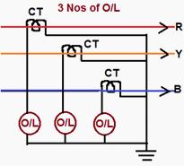
Over current relays generally have 50% to 200% current setting while earth leakages over current relays have either 10% to 40% or 20% to 80% current settings.
One important thing to be noted here is that the connection of the star points of both the C.T. secondary’s and relay windings by a neutral conductor should be made.A scheme without the neutral conductor will be unable to ensure reliable relay operation in the event of single phase to earth faults because the secondary current in this case (without star-point interconnection) completes its circuit through relay and C.T. windings which present large impedance.
It is not sufficient if the neutral of the CTs and neutral of the relays are separately earthed. A conductor should be run as stated earlier.
2. 3 No O/C Relay+ 1 No E/F Relay for Overcurrent and Earth Fault Protection
The scheme of connection for 3 Nos Over current Relay 1 No Earth Fault Relay is shown in figure below. Under normal operating conditions the three phase fault conditions and current in the 3-phase are equal and symmetrically displaced by 12 Deg.
Hence the sum of these three currents is zero. No current flow through the earth fault relay.
Figure 2 – 3 No O/C Relay+ 1 No E/F Relay for Overcurrent and Earth Fault Protection
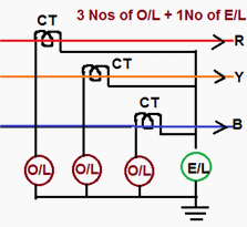
In case of phase to phase faults (say a short between R and Y phases) the current flows from R-phase up to the point of fault and return back through ‘Y’ phase. Thus only O/L relays in R and Y phases get the fault and operate.
Only earth faults cause currents to flow through E/L relay. A note of caution is necessary here. Only either C.T secondary star point of relay winding star point should be earthed. Earthing of both will short circuit the E/L relay and make it inoperative for faults.
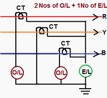
3. 2 No O/C Relay + 1 No E/F Relay for Over Current and Earth Fault Protection
The two over current relays in R and B phases will respond to phase faults. At least one relay will operate for fault involving two phase. For fault involving ground reliance is placed on earth fault relay. This is an economical version of 3-O/L and 1-E/L type of protection as one overcurrent relay is saved.
With the protection scheme as shown in Figure complete protection against phase and ground fault is afforded.
Figure 3 – 2 No O/C Relay + 1 No E/F Relay for Over Current and Earth Fault Protection
Current Transformer Secondary Connections
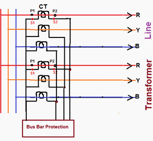
For protection of various equipment of Extra High Voltage class, the star point on secondary’s of CT should be made as follows for ensuring correct directional sensitivity of the protection scheme.
Transmission Line , Bus Bar and Transformer:
- For Transmission Lines – Line side
- For Transformers – Transformer side
- For Bus bar – Bus side
Figure 4 – Transmission Line , Bus Bar & Transformer scheme
Generator Protection – Generator Side
Figure 5 – Generator protection scheme
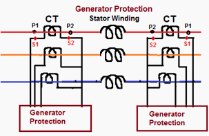
The above method has to be followed irrespective of polarity of CT’s on primary side. For example, in line protection, if ‘P1’ is towards bus then ‘S2’s are to be shorted and if ‘P2’ is towards bus then ‘S1’s are to be shorted.
Standard Overcurrent and Earth Fault Protection
| No | Equipment Name | Protection |
| 1 | 11 KV Feeders | A) 2 No Over Current and one no Earth Fault IDMT relays |
| B) 2 No Instantaneous Overcurrent (highest) and one no Instantaneous Earth fault relay | ||
| 2 | 8 MVA Capacity OR Two Transformer in a Substation (Irrespective of capacity) | HV side: 33 KV Breaker (Individual or Group Control with 3 Over Current and One Earth Fault IDMT relays LV Side: Individual 11 KV Breakers with 3 Over Current and One Earth Fault IDMT relays |
| 3 | 8 MVA Power Transformer | Differential relays OR REF relays on LV side |
| 4 | Only one PTR in a Sub Station (Less than 8 MVA) | HV Side: HG fuse LV Side: 11 KV Breaker with 3 Over Current and one E/F IDMT relay |








I did learn lot of technical question from this portal.
Question-answer for electrical interview
R/SIR PL.SEND ME U R DAILY COMMENTS ON ELECTRICAL
Really helpful information but can I use one overcurrent relay on 3 current transformers
Dear sir,
why double set of c.ts (both ends) used in overcurrent protection ?
pl explain
Dear sir
Good evening
I want un example of calculate of astudy case of fault happen on transformer and fixed instantaneous over relay on it .I need to calculate IR , TAP.,IF,AND TIME OF TRIP and i need what doesn’t mean taps
In 2 No O/C Relay + 1 No E/F Relay for Over Current and Earth Fault Protection, which relay will operate for Y phase over current (not phase to phase fault)?. if Earth fault relay it wont be a wrong information that earth fault instead of phase overcurrent?
How directional senstivity will be stable when CT star point are towards equipment under protection?
@M.Iqbal, check out http://gpac.link/1Tjlm6d the video tutorial on http://generalpac.com goes over wye/star connected CTs and how they are grounded.
please do send me newsletters
i am really interested in site. hope you will accept me as a member. thank you.
Thank for the information.
Thnx for the information. However i would like to know in case of 2 o/c +1 e/f Protection scheme what would be the changes in the operation of relays if star point of CT secondaries is earthed instead of star point of relay windings as you have shown. There is a confusion because many people show the star point of CT secondaries earthed, which one is correct? Actually I am from J&K state and devastating floods have destroyed many of our 33/ 11 kV sub-stations and we are engaged in power restoration o war footing basis. I am encountering this confusion while rewiring of 33 kV C&R panels & 11 kV VCB panels. Your suggestion would be appreciated.
Thanks & regards
Mohammad Iqbal
J.E PDD J&K.
You are right, Star point of ct secondary is grounded at CT junction box and one wire(usually black) called neutral is goes to the relay from that star point.This neutral wire is complete the circuit of relay..(it is the returning path)
I am a learner Technician and this page has helped me a lot.