
Internal arc testing of MV switchgear
The aim of this article is to describe the internal arc phenomenon, its consequences for safety, current methods of limiting them and current regulations in general for equipment used in medium-voltage electrical distribution networks.
Internal arcs can occur in electrical equipment when the service conditions for which it was designed are not fulfilled or it has an inherent fault or a fault originating from incorrect installation. To this end, Chapter of IEC 62271-200 provides a guide to the usual origins of internal arcs, as well as how to reduce the likelihood of them occurring.
Typical examples are network overvoltages, inappropriate equipment specification, inadequate protection curves, incorrect use of equipment, use of equipment after the end of its rated service life or rated electrical endurance, inadequate preparation of cable terminals, inadequate routine production checks, etc. But it has to be said that although the risk is low if all the electrical requirements are fulfilled, it is not non-existent, as experience has shown.
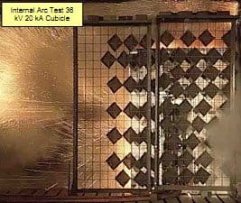
Human error and particular circumstances that may arise at any given moment on an installation are not totally controllable, and sadly the consequences of a fault can be very serious for anyone in the vicinity.
Given that this type of equipment is found throughout the distribution network in both buildings to which the public is admitted and areas with unrestricted access, safety (of operators and the general public) must be taken into account in the design of equipment and installations to minimise the risk of internal arcs occurring. This is the gist of, for example, ITC16 of the Spanish Regulation on Power Plants and transformer substations.
In addition to the construction aspects specific to each device in which the manufacturer has to take steps to minimise the risks of an internal arc occurring, it is understood to be vitally important that users, installers and designers of Medium Voltage installations are familiar with the installation conditions stated by the manufacturer and thus avoid risks.
Standards framework

There are a number of current international standards which describe a method of classifying metal-enclosed electrical equipment IEC 62271-200, insulation-enclosed electrical equipment IEC 62271-201 and prefabricated transformer substations IEC 62271-202, according to their protection of people in the vicinity when an internal arc occurs in high-voltage switchgear compartments up to 52 kV.
At present there are only standardised tests for checking the consequences of internal arcs in high-voltage switchgear, but not in power transformers or low-voltage switchgear. This may be justified by the fact that the greatest short circuit power is on high-voltage switchgear, and transformers are usually protected with lightning arresters which reduce the likelihood of internal arcs on their high-voltage side due to overvoltages, and/or by means of current limiting fuse-links inserted upstream of them. However, when there is only a circuit-breaker upstream of a transformer, the likelihood and consequences of an internal arc on the medium-voltage side are unlimited.
The arc is usually generated (for the test) by passing current across a fine copper wire arranged for this purpose between conductors or conductor and earth. In the case of prefabricated substations initiation occurs in the MV equipment and in the MV interconnection between this and the transformer.
There are some electricity company specifications (e.g. EDF) which generate internal arcs by attempting to break a higher current than the equipment itself is capable of breaking. In other words it assesses what would happen if an operator were to switch the device and it were not capable of breaking the current.
It is important to describe how the internal arc test is carried out differently when access is by specialist personnel or the general public. In both cases supports are placed with fabric samples in the accessible area(s) around the equipment, varying the type of fabric and the distance from the equipment depending on whether it is wished to assess accessibility by the public or specialist personnel, being stricter for the first group of people.
Consequences of an internal arc
Internal arcing is a very quick, almost explosive, phenomenon which converts the initial electrical energy into the generation of a wave of pressure and heat in the medium where it occurs, typically the dielectric medium used.
The diagram below attempts to explain how this develops.
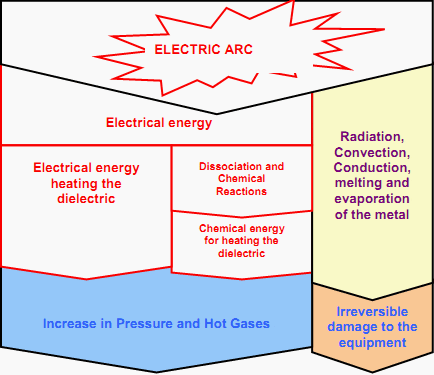
The effects or consequences of a fault or internal arc are as follows
Pressure wave
The pressure wave has two consequences. The first is on the actual equipment enclosure which should resist such mechanical force and the second is on the room where this equipment is located, which also suffers the consequences of the violent increase in pressure. This could cause serious damage to its structure (windows, doors, brick walls). This pressure wave is much more violent when a larger amount of gases has been generated (typical in the case of liquid dielectrics).
Release of hot gases
The internal arc will cause an increase in temperature of the gases given off by the equipment’s materials due to the electrical energy transmitted to the dielectric medium and also the chemical energy through dissociation or chemical reaction of the dielectric and gases generated.
Depending on the circumstances, this chemical reaction can be strongly exothermic depending on the materials and dielectrics used and can cause fire if there are any combustible materials in its vicinity, or cause burns to people nearby or outside the room through flues and ventilation grilles.
Puncturing of the equipment enclosure
As it develops, the arc may puncture the enclosure, if it is in contact with it or very close to it. In this case very high-intensity radiant heat will be produced that could cause serious burns to anyone standing close by.
Irreversible damage to the equipment
The energy generated inside can cause the metal parts which make up the enclosure to be damaged by a rapid increase in pressure or by melting and partial evaporation of the metal parts. By way of example, in an internal arc of 20 kA for 0.5 s, the dissipated electrical energy can typically be 8 MJ.
Propelling of parts of the equipment
During this process parts of the inside of the equipment, and of the enclosure itself, may be ejected, which could seriously affect any people in the vicinity.
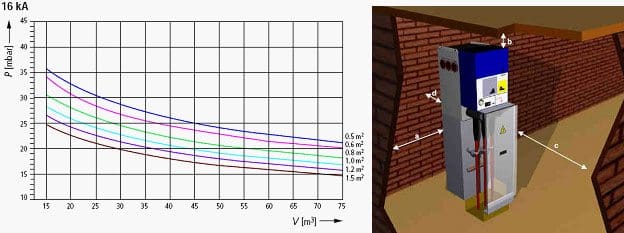
All these effects are assessed during internal arc testing since these are the test acceptance criteria. The effects of the pressure wave in the room are only assessed during internal arc testing in prefabricated transformer substations.
Systems for limiting the effects of internal arcs
To avoid the above effects, MV equipment manufacturers have provided these with a number of systems to avoid harm to people or damage to equipment.
There are two types of prevention method or system from the point of view of their means of action:
Passive systems
These are systems that naturally or by design prevent the effects of either hot gases or pressure waves without any mechanism or intelligent system intervening. Systems recognised as passive elements could be the following:
Bursting disc
This is an element that breaks or is released at the time the pressure increases, allowing the gases to escape. This escape will be into a controlled area far away from areas that can be accessed during operation.
Enclosure design to cope with overpressure
When faced with increased pressure in its interior the equipment must be able to withstand it, deforming as little as possible and allowing the gases to flow out of it in a controlled form avoiding harm to anyone.
It must be said that in its first instants the internal arc is a phenomenon that is practically adiabatic, generating overpressure similar to water hammer. In our experience the air pressure inside the equipment can increase to 2.1 bar (relative) in 30 ms. No protection system (with the exception of fuses) located on the distribution network is capable of eliminating the fault in such a short space of time, therefore the enclosure must be able to withstand it.

There are simulation technologies using finite elements which can help with the design of the equipment but these must be tested and checked by creating an internal arc. Simulation is no substitute for the actual test.
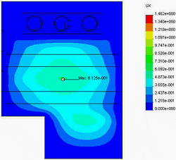
Expansion ducts
In addition to bursting discs, the equipment may have a duct which evacuates the gases to controlled areas without producing any external damage. The duct may be constructed using an actual conduit or by placing the equipment within the room maintaining some defined distances, for example, the space between a metal-enclosed switchgear device and the back wall.
Control of the electric arc
The electric arc inside the equipment can be controlled in such a way that it causes the least damage possible. The energy transmitted by the arc is proportional to the current which circulates through it and to the term known as arc voltage. This voltage depends on the dielectric, but is proportional to the length of the arc. If the equipment is designed for this arc length always to be the same and to be small, it will be possible to control the energy generated in it and thus minimise the damage. Hence, the equipment has starters or sacrificial elements inside for the case of an internal arc. To ensure correct operation it would be necessary to place arc starters in order to cover all possible arc situations in the equipment (failure to break, different power supplies, different arc origins, etc).
Cooling Systems for the hot gases
These involve ducts or elements which cool the expelled gases. One form of doing this for example is by means of a labyrinth for the gases to escape giving contact with a higher metal surface area so that they lose their calorific power. Another system is one that uses refractory material so that this absorbs the excess heat as the gases exit.

Fuses
These elements limit the duration and energy of the arc in the circuit downstream of it. This is deemed to be a passive element since its design means that its microjunctions melt when high current passes across it, there being no electronic element or mechanism.
Active systems
These are systems which by nature are mechanical and/or electromechanical systems which limit the duration of an internal arc. They consist of the following types:
Breaking elements combined with protection relays
These are deemed to be any circuit-breaker or control device which actuates and eliminates the fault on command from a protection relay which determines whether a fault exists or not, depending on its calibration. This does not limit the pressure wave, but does restrict the total dissipated energy, depending on how long the current passes.
Short-circuiting elements
These elements operate by closing an earthing switch upstream of the fault, short-circuiting the power supply and extinguishing the arc as the arc has greater impedance than the earthing switch conductors. These short-circuit devices must be installed on any of the possible points where the fault is supplied with power. However, they need to be combined with an actuator or trip which discriminates whether or not an arc exists in the equipment.
These associated elements must be arranged in the compartments existing in the equipment since all compartments are at risk of internal arcs. The following types of associated elements exist:
- Overpressure presence indicating system. These actuate in response to a dynamic increase in pressure which sends a mechanical or electrical signal to the short-circuit device or operating relay.
- Brightness presence indicating system. These actuate in response to the brightness of the internal arc inside the equipment. These elements require an auxiliary power supply.
Equipment classification according to its behaviour faced with an internal fault
The current international standard IEC 62271-200 defines the so-called IAC “Internal Arc Classes” which require the equipment IP rating in response to internal arcs to be defined with four parameters:
- Accessibility: Front (F) and Side (L) and/or Rear (R)
- Amplitude of the short-circuit current: for example, 16 kA
- Arc duration: for example, 0.5 s
- Access limited to authorised personnel or free access
In order to classify a device as IAC, it must pass the test in all its high-voltage compartments.
Both the fault and its duration can be used to establish how robust the equipment is when faced with an internal arc, since it is up to the user to determine whether this limiting of the arc and time is compatible with the network and thus minimise risks and damage in the face of a possible fault.
In all cases it needs to be checked by testing that the equipment behaviour is as defined by the manufacturer in terms of management of the hot gases produced, and that there is no risk of burns or impact for anyone nearby in the areas defined as accessible during operation.
The international standards mentioned only assess and classify the equipment response to an internal arc depending exclusively on the behaviour of its passive elements, since what they claim to do is to assess its safety when any of its high-voltage components suffer a fault that triggers an internal arc in them. In this sense those components considered to be passive safety elements are those which are structural or with a very low probability of failure, such as fuses, due to their absence of electronic mechanisms or devices.
In summary, no active protection can be used as an internal arc risk prevention system unless it has been designed so that it is able to pass the test without actuating the active component.
For example, equipment with cut-outs or circuit-breakers needs to be tested with its protection relay disabled. During its service life, if this device suffers an internal arc, the relay will be able to operate, but always with the safety of knowing that if this does not work or is damaged by the arc, the equipment is intrinsically safe. Taking the example of a motor vehicle, passive systems are the safety belt and the car chassis design while an active system would be the airbag. The former are always mandatory while the second is optional.
Factors which influence the behaviour of an internal fault
The behaviour in the case of an internal fault basically depends on:
- Layout of the conductive parts,
- Materials which make up the conductive parts,
- Volume and geometry of the affected compartment,
- Insulating materials (gas, liquid, solid) in the vicinity of the arc,
- Whether or not the phases are segregated,
- Value of the current,
- Arc duration,
- Number of simultaneous arcs possible,
- Place where the arc is initiated and/or fixed,
- Speed of expulsion of the gases produced by vaporization, decomposition and/or chemical reaction of the materials present,
- Chemical reaction of the hot gases or liquids in contact with the air.
Nevertheless the behaviour is specific to each device, installation method and test procedure.
Usually, for reasons of convenience for laboratories, equipment which uses SF6 as an insulating gas is tested against an internal arc with air instead of SF6, which gives rise to a more violent phenomenon (faster increase in pressure). This is therefore a more stringent condition permitted by international standards.
However, substitution of other gases and insulating liquids is not permitted. In this sense it can be said in general that insulating liquids generate a large amount of gases that are easily inflammable on contact with air, should be they be subject to an electric arc. Hence, and although it is not usually used in the latest equipment, numerous laboratories have suffered unexpected explosions in this type of equipment, when an accidental internal arc occurs in them.
Conclusions
A device which has the capacity to withstand an internal arc is a safe element as long as it has been installed correctly and the surrounding conditions are correct. For this, systems will have been set up that the manufacturer deems necessary to limit its effects.
The effect-limiting systems are active or passive, only the latter being valid for checking the behaviour faced with internal arcs.
Each device has a specific behaviour faced with internal arc situations. Hence, the use of devices which limit the duration of the arc to minimise the damage this can produce, must be linked to known information by testing the behaviour of such equipment in an internal arc situation, without using devices which limit its duration.
Devices which limit the duration of the arc may be a very valid means of reducing the effects of the internal arc both on the equipment itself, should it be possible for it to be repaired, and on people and premises.





very nice article on the internal arc subject, I wanted to give some more detail on the issue of active protection, now listed as well in IEC – 200 for IA effects mitigation.
As IA protection is all about risk of an event and consequences to personell safety and equipment availability ABB has defined a risk mapping approach to propose IA mitigation active solution both in new SWG and more important in old installed base where the SWG design was not IA proof.
see concept:Arc Fault Protection Solutions, IEC Brochure
www05.abb.com/…/Arc%20fault%20protection%20solutions_broch_756596_LRENa.pdf
for links to the more advanced active mitigation solution see UFES: Ultra Fast Earthing Switch: http://www.abb.com/product/db0003db004279/05d1e893194566e9c1257799003303d7.aspx
Thanks for valuable article on internal arc & personnel safety
You’re welome Shivakumar! Glad you find it usefull!