
Estimated Study Time: 14 minutes
Contactors For Motor Control
Motor control gear and associated circuitry are fundamental parts of electrical distribution and utilisation systems. Motor control gear in its simplest form may be a direct on-line starter consisting of a switching device (contactor) and tripping device (overload relay) mounted within an appropriate enclosure.
 Contactor As An Important Part Of The Motor Control Gear (on photo: Fried contactor in a star/delta panel; credit: dave via Flickr)
This technical article will deal with a.c. contactors, as they are the major components utilized in motor control gears (beside overload relays).
Contactor – The Switching Device
The most widespread switching device used in a starter is the a.c. air-break contactor which consists of contact assemblies actuated by electromagnetic action. An operating coil is enclosed by the magnetic yoke, and when energized attracts an armature to which is attached a set of moving contacts which make with a set of stationary contacts.
Modern contactors use a silver alloy contact tip, normally silver–cadmium oxide or silver–tin oxide alloy attached to a brass or copper backing strip. The choice of tip material is critical, and is normally established after many type tests.

The contact materials are selected primarily for their weld and erosion resistance – the suitability of the material chosen is then confirmed by a sequence of type tests and special tests, such as contact life tests.
The silver alloy typically contains 10–12% cadmium oxide or tin oxide. The use of silver–tin alloys is now the first choice at the design stage as the cadmium can require special precautions during manufacture, and ultimately in the disposal of the contacts.
Modern contactors use double-break main contacts, usually of butt-type design, with either circular or rectangular contact tips.
It must always be remembered that the attachment to the backing strip requires a silver enriched backing – this means that older maintenance techniques such as filing of contact faces actually reduce contact service life and will eventually expose the silver backing.
This may permit contact welding.
Larger sizes of contactor usually require the use of cooling devices inside the arc chamber to assist with arc extinction. These may take the form of cooling plates or shrouds which simply enclose the contacts, or an array of de-ion plates similar to those in a circuit breaker.
The cooling plates or de-ion plates do not need to be selected for their electrical conducting properties. In most cases the material used should have a relatively high melting point and mild steel can be used.

Breaking Arc Speed – In all cases the objective is to put the arc out within typically 10–20ms when breaking currents of eight times the rated AC3 value under type test conditions, and 5–10 ms in normal service. The relatively fast arc extinction is a major consideration where long service life (termed durability in British and International standards) is a design objective.
An AC3 contact life of 1–2 million operations can be achieved with modern designs.
Another choice the designer must make is that of insulating materials. These not only act as a mounting base but as the mechanical slides and guides and also the wall of the arc chamber within the contactor.
The use of asbestos has now been phased out by all manufacturers with replacement materials being adopted for the continued production of existing designs.
How it works?
The contactor is magnetically held closed by maintaining the current flow through the coil. If the voltage to the coil fails or falls below a defined level, the contactor opens, thus disconnecting the motor from the supply. The coil must be constantly energised in order to keep the contactor closed.
Alternatively, contactors can be fitted with a mechanical latch which does not require continuous energisation.
Operation – In order to provide quiet operation, a.c. magnets are fitted with shading rings which normally consist of a single short-circuited loop of copper alloy. They fulfil the basic function of providing a secondary magnetic flux to prevent the magnetic pole faces parting and reclosing when the flux produced by the operating coil passes through zero.
If a shading ring should be omitted when reassembling some types of contactor after maintenance, the omission will be obvious as the magnet will ‘hum’ loudly when energised.
This same situation may also arise if a shading ring should break in service, although this is unlikely as modern contactors have captive shading rings of proven design.
The remaining design parameters such as the ability of terminals to accept cables, service temperature rise limits, the ability to switch currents under defined conditions and the performance under short circuit conditions, are now determined by British and International standards.
The standards applicable to low voltage motor controlgear are mandated CENELEC publications. Compliance with these satisfies the requirements of the Low Voltage Directive and the Electromagnetic Compatibility Directive and permits the use of the CE mark after drawing up the appropriate Technical Construction File and Declaration of Conformity.
Contactor Selection
Contactors for use in direct on-line starters are normally selected by their AC3 rating, that is the switching on of a cage type induction motor and switching off the supply to the motor after the motor has run up to full speed.
The other most common utilisation categories are AC4, the switching on and off of a cage type induction motor before it has run up to full speed, sometimes termed ‘inching’ or ‘jogging’ the drive, and category AC2, the switching of the stator supply to a wound rotor motor where the starter circuit automatically inserts resistance into the rotor circuit for each start.
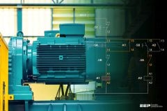
Figure 1 shows a star-delta starter.
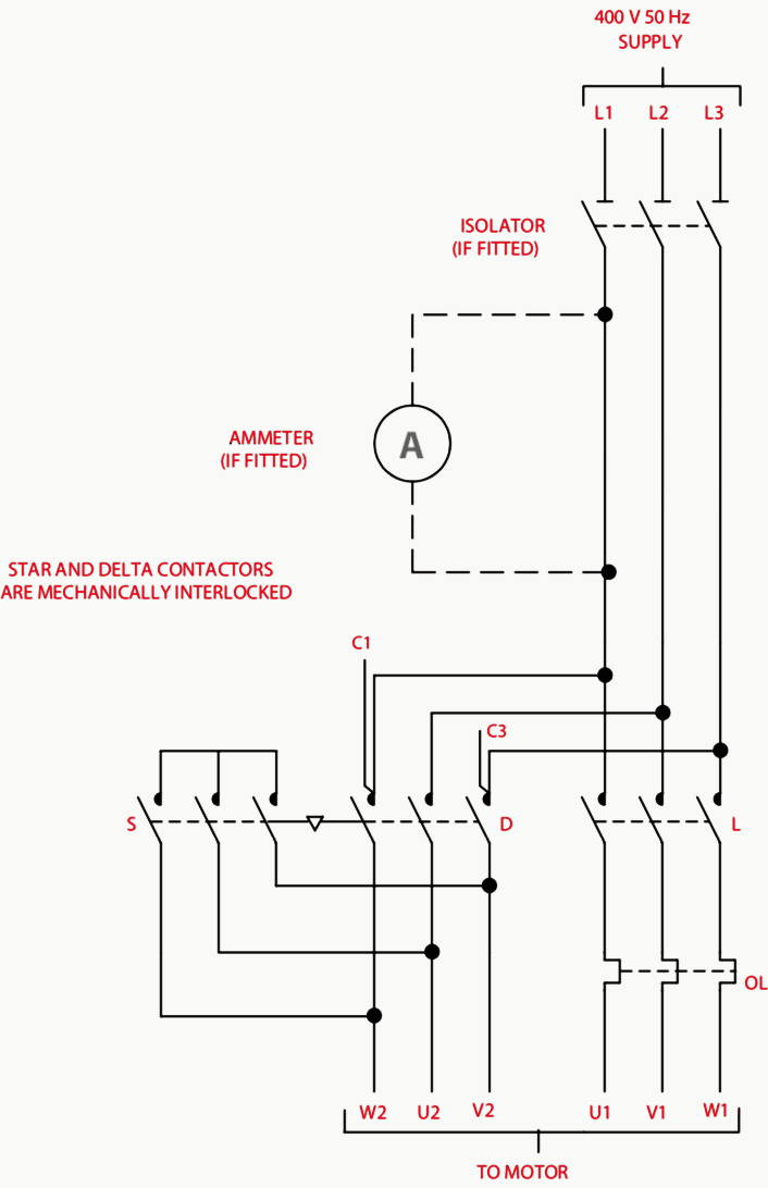
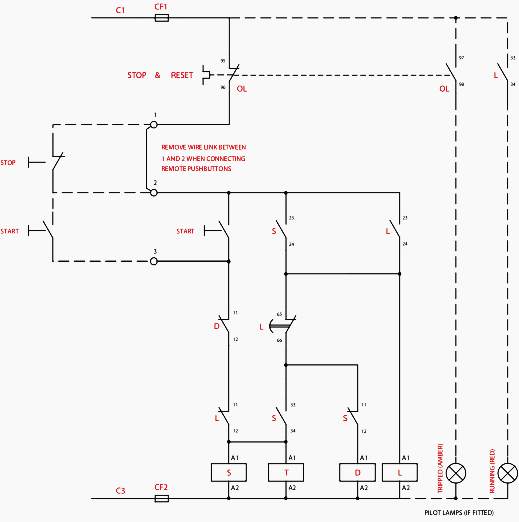
Table 1 – Contactor utilisation categories
| Utilization Category | Current as multiples of operational current (Ie) | ||||
| Normal Operation | Proving Operation | ||||
| make | break | make | break | ||
| AC1 | Non-inductive or slightly inductive loads such as furnaces and heating loads | 1 | 1 | 1.5 | 1.5 |
| AC2 | Starting of slip ring motors. Plugging with rotor resistance in circuit | 2.5 | 2.5 | 4 | 4 |
| AC3 | Starting of cage motors, switching of motors during running | 6 | 1* | 10 | 8 |
| AC4 | Starting of cage motors, plugging inching | 6 | 6 | 12 | 10 |
The catalogued ratings are published on the basis of known service conditions, typically:
- Ambient temperature outside the starter enclosure between -5° and 35°C average (with a maximum not exceeding 40°C).
- Rate of operation to be specified by the manufacturer, typically 120 starts per hour.
- The duty cycle or utilisation category – see Table 1 for typical values of current to be switched during type testing and in service, e.g. is the starter a reversing type which must reverse a motor which is already run up to speed, or does the reversing only occur after allowing the motor to come to rest? In the latter case only AC3 rated contactors could be used.
- The acceleration time of the drive, the ability of the contactor to carry the starting current, must be considered.AC3 rated contactors are able to carry eight times rated current for a minimum of 10 s (this applies to ratings of up to 630 A – above this the value is six times rated current).
- Any special contact life requirement.
- The type of short-circuit protective device to be installed in series with the supply to the starter, and the classification of type of protection to be obtained.
- Any special co-ordination requirement, e.g. are there any residual current devices, which on detecting a fault condition may attempt to open the contactor on a current in excess of its breaking capacity.
- Any special requirement to attach cables of other than copper cored, PVC or rubber insulated types to the contactor terminals, e.g. the use of some types of high temperature insulation such as XLPE allows the cable to run much hotter than the manufacture expected.The normal practice is to design for use with 70°C cable so the possible economies of using XLPE may be not be exploited as the core temperature may be as high as 250°C, consequently the cabling would act as a heat source, not a heat sink.
Any of the above may need special consideration and may necessitate the selection of a contactor of a higher AC3 rating than catalogued values would initially suggest.
Final or run contactors used in auto-transformer starters should be selected using AC3 ratings (see Figure 2) .
Star and intermediate contactors should be selected in accordance with catalogue recommendations.
For stator-rotor starters, the stator contactors should be selected using AC2 ratings. Rotor contactor ratings are normally specified by the contactor manufac- turer as enhanced ratings based on them being in circuit only during starting.
Another important consideration when selecting contactors is to ensure that the proposed cable conductor can be accommodated by the contactor terminals. Most manufacturers supply this information in their catalogue together with the different types of termination that are available.
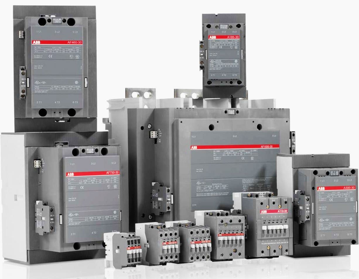
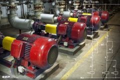
A range of contactors is illustrated in Figure 3 below.
Reference // Handbook of Electrical Installation Practice by Geoffrey Stokes
Related electrical guides & articles


Edvard Csanyi
Hi, I'm an electrical engineer, programmer and founder of EEP - Electrical Engineering Portal. I worked twelve years at Schneider Electric in the position of technical support for low- and medium-voltage projects and the design of busbar trunking systems.I'm highly specialized in the design of LV/MV switchgear and low-voltage, high-power busbar trunking (<6300A) in substations, commercial buildings and industry facilities. I'm also a professional in AutoCAD programming.
Profile: Edvard Csanyi

To feed a 9 kW DC motor at the voltage level of 220 VDC, we have two normally closed(NC) contactors in the design, each of which has two closed blades, and both blades are placed in the positive and negative poles of the motor (4 contacts in total), in order to withstand We have put the power of the contacts at the voltage level of 220 VDC. Is this design approved and will it not be a problem?
Good for electrical maintenance technician.
Good information received
Good for electrical consultants and contractor pls update me the
Nicely explained.