
Estimated Study Time: 15 minutes
Choosing the right transfer switch
Transfer switches support multiple operation modes (manual, automatic, non-automatic, bypass isolation, etc.) and feature a range of different switching mechanisms (contactors, circuit breakers).
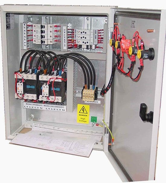
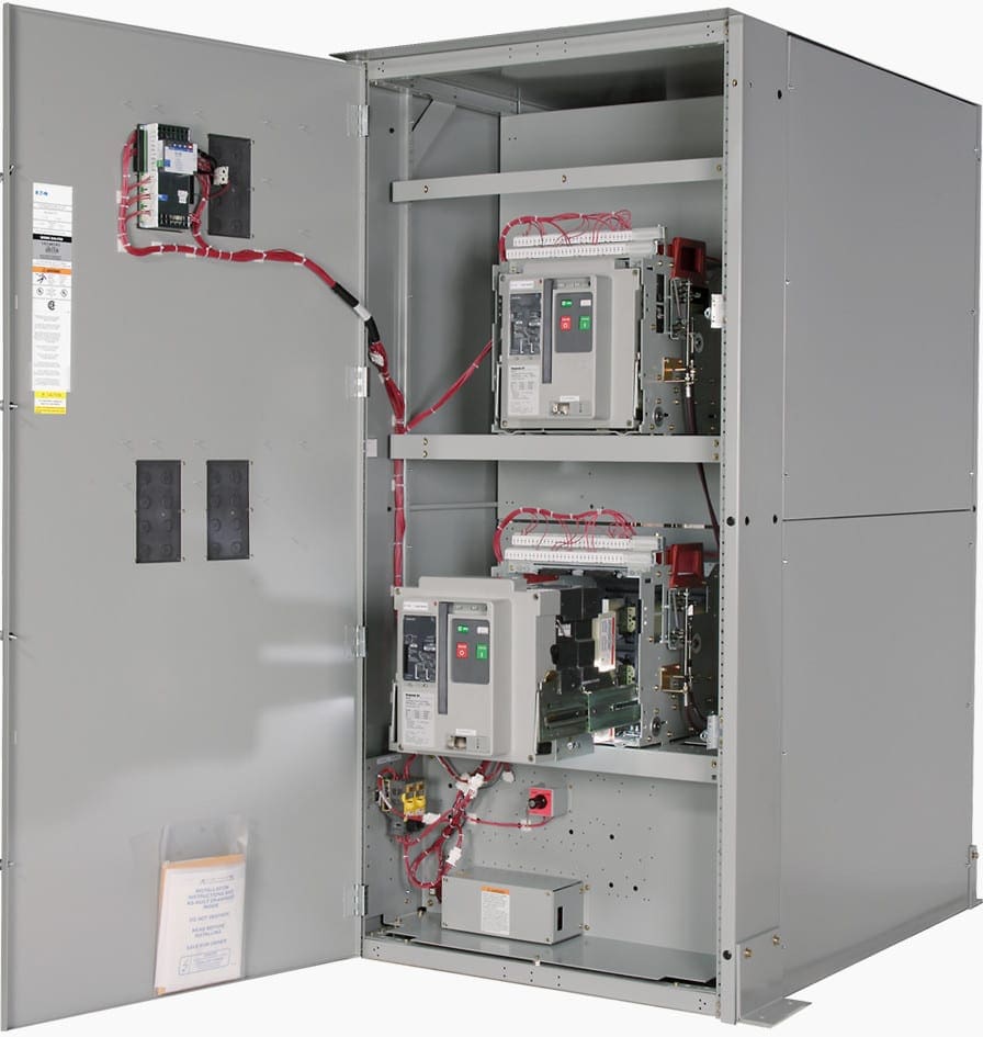
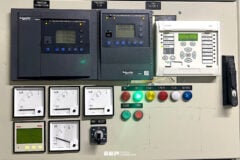
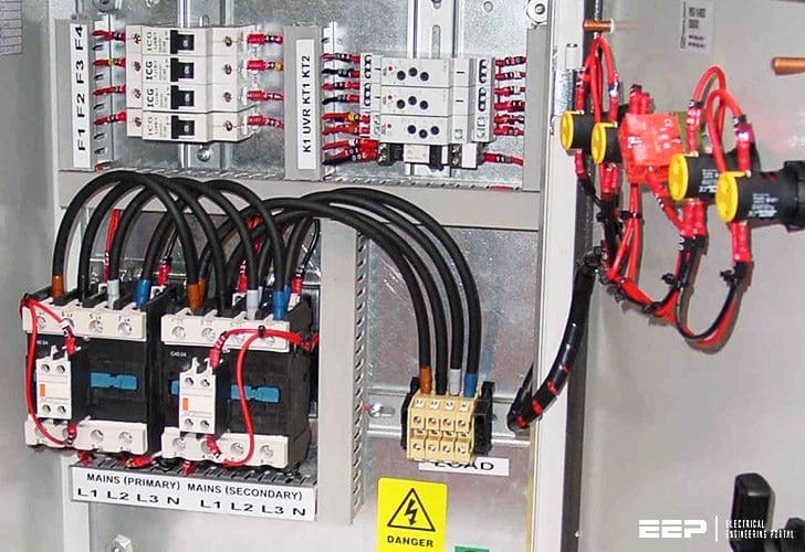 Should transfer switch be equipped with contactors or circuit breakers? (on photo: Eaton Manual Transfer Switch)
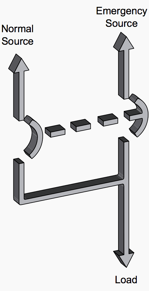
Transfer switches are used to protect critical electrical loads against loss of power. The load’s normal power source is backed up by a secondary (emergency) power source. A transfer switch is connected to both the normal and emergency power sources and supplies the load with power from one of these two sources.
Transfer can be automatic or manual, depending upon the type of transfer switch equipment being used.
Once normal power is restored, the load is automatically or manually transferred back to the normal power source, again depending upon the type of transfer equipment being used (Figure 1).
How ATS works? (starting with basics…)
In automatic transfer switch equipment, the switch’s intelligence system initiates the transfer when normal power fails or falls below a preset voltage. If the emergency power source is a standby generator, the transfer switch initiates generator starting and transfers to the emergency power source when sufficient generator voltage is available.
When normal power is restored, the transfer switch automatically transfers back and initiates engine shutdown.
In the event the normal power source fails and the emergency power source does not appear, the automatic transfer switch remains connected to the normal power source until the emergency power source does appear.
With the help of the information in this technical article, however, electrical designers can sort through their options and choose the right switch for their specific requirements.
Contents:
So, let’s start the discussion following the below contents.
- Switching mechanism of a transfer switch:
- Contactor type
- Circuit breaker type:
- Operation modes of a transfer switch:
Switching mechanism
The switching mechanism of a transfer switch is the part that is physically responsible for carrying the rated electrical current and shifting the connection from one power source to another (main to backup source).
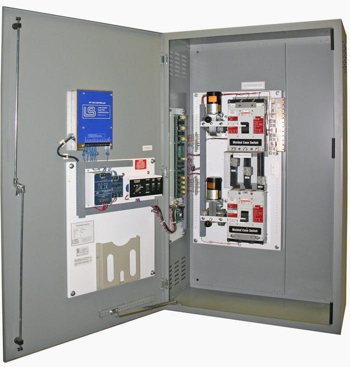
LV switching mechanism technology comes in two basic types, commonly referred to as contactor type and circuit breaker type. Circuit breaker switching mechanisms can be further divided into two sub-types: molded case (up to 1000A) and power case (1000A up to 5000A).
1. Contactor switching mechanisms
This is the most common and affordable switching mechanism type. In most cases, contactors are constructed as a double-throw switch where a single operator opens one set of power contacts while closing a second set.
In an open transition design, a mechanical interlock is often employed to prevent simultaneous closure of both contact sets. In a closed transition design, the mechanical interlock is absent.
Advantages
- Contactor switching mechanisms support all three transition types: open delayed, open in-phase, and closed
- Transfer switches equipped with a contactor switching mechanism are generally the most economical
Disadvantages
- Contactor switching mechanisms don’t include integral overcurrent protection, so the power contacts are not self-protecting. In the event of a fault, the contacts will typically remain closed and future viability is dependent on other protective devices in the electrical circuit, eliminating the condition
- At rated amperage, WCR may be lower when compared to a circuit breaker switching mechanism
2.1 Molded case switching mechanisms
Routinely used for closing and interrupting a circuit between separable contacts under both normal and abnormal conditions, molded case switches feature simple designs and are capable of supporting either a mechanically operated, over-center toggle or a motor operator.
They are typically assembled in an enclosed housing constructed of insulating material.
Molded case switching mechanisms provide a compact, cost- effective and service entrance-rated solution, as they eliminate the need for additional upstream protective devices.
Each molded case mechanism individually complies with industry standard UL® 489, which covers low voltage molded case switches and circuit breakers.
Advantages
- Contacts are self-protecting at high fault currents due to integral magnetic sensing.
- Molded case switching mechanisms can be configured with integral overcurrent protection that provides “lock-out” functionality and eliminates automatic transfers into a fault condition.
- Users can manually operate them under load due to “quick make/quick break”, over-center toggle switching action.
- Molded case switching mechanisms provide high withstand close-on rating (WCR) at lower amperages, eliminating the need to oversize transfer switch frame size to meet specification requirements.
Disadvantages
- Molded case switching mechanisms are generally more expensive than contactor switching mechanisms.
- Molded case switching mechanisms don’t support closed or in-phase transitions.
Molded case switching mechanisms are ideal for loads up to 1000 A that require a compact, high-capacity transfer switch with built-in fault protection.
2.2 Power case switching mechanisms
Power case mechanisms are larger, faster and more powerful than molded case mechanisms, and capable of handling up to 5,000 amps. The two-step stored energy technology they utilize can be operated both mechanically and electrically, and some models feature integral overcurrent protection similar to what’s typically found in molded case designs.
Each power case mechanism individually complies with industry standard UL 1066, which covers low voltage power case breakers.
Advantages
- Power case switching mechanisms can be configured with a variety of trip unit types that provide integral, programmable overcurrent protection, ground fault sensing, power quality metering, and diagnostics.
- Power case switching mechanisms offer the highest withstand and amperage ratings of any switching mechanism design.
- Rapid closing speed facilitates in-phase and closed transitions in addition to delayed transitions.
- Unlike both contactor and molded case mechanisms, power case switching mechanisms can be configured for “selective coordination”.Selective coordination allows the protective device located immediately upstream of an electrical fault to open first, leaving the rest of the power distribution system operational. For many applications, including emergency, critical operations power systems and legally required systems, use of selective coordination is mandatory.
Disadvantages
- Power case switching mechanisms are larger than contactor and molded case designs.
- Power case switching mechanisms are typically the most expensive of the three switching mechanism types.
Transfer switch operation modes
Power transfers involve two processes: initiation and operation. Initiation is what starts the transfer. Operation is what completes it. Most transfer switches can support multiple operation modes through the addition of configurable options.
1. Manual mode
In manual mode, both initiation and operation are performed manually, typically by pushing a button or moving a handle.
Advantages
- With molded case or power case designs, transfers can occur under load as a failsafe if the automatic controller and/or control circuitry sustain damage or become inoperable.
- Human operator has maximum control over the transfer process
- Transfer is independent of the automatic controller
Disadvantages
- An operator must be physically present to initiate a transfer – even overnight and on weekends
- Transition delay time is dependent on the operator and therefore may increase when compared to automatic mode transfers, which are described below
- Limited to open delayed transitions, as open in-phase and closed transitions require microprocessor logic to manage source synchronization
- On some transfer switch designs, operators must open an outer safety door to access the switching mechanism, exposing them to energized electrical equipment and potentially requiring them to wear personal protective equipment
- Facilities with emergency and legally required installations are usually prohibited by law from using manual mode unless their transfer switch is capable of performing an automatic transfer in certain especially urgent situations
2. Non-automatic mode
In non-automatic mode, the operator manually initiates a transfer by pressing a button or rotating a switch that causes an internal electromechanical device to electrically operate the switching mechanism.
Advantages
- As with manual mode, operators are in complete command of transfer initiation
- Transitions complete more rapidly than with manual mode because of the electromechanical device that electrically operates the switching mechanism
- Non-automatic transfer switches tend to cost less than an automatic type
Disadvantages
As with manual mode, a human operator must be present to initiate a transfer, and there’s no support for open in-phase or closed transitions.
3. Automatic mode
In automatic mode, the transfer switch controller completely manages both initiation and operation. Initiation is triggered when the automatic controller senses an unavailability or loss of source power and operation is typically performed by an electric solenoid or motor.
Advantages
- Transfers and re-transfers can be completed in the shortest time possible
- As the transfer switch executes the entire transition process itself, there’s no dependence on a human operator
- Users enjoy greater flexibility, as they can select from automatic, non-automatic, and manual operation modes using programmable set points and/or an integral control panel
- Automatic mode meets NEC requirements applicable to emergency and legally required systems
Disadvantages
Automatic transfer switches tend to cost more than devices that operate only in manual or non-automatic mode
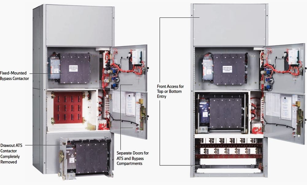
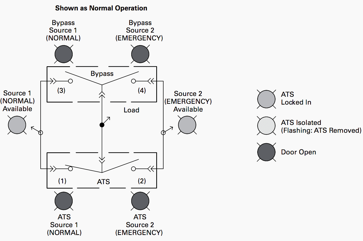
4. Bypass isolation mode
Traditional transfer switches feature a single switching mechanism. In contrast, bypass isolation transfer switches include dual switching mechanisms that provide redundancy for critical applications.
During repair or maintenance procedures, a technician can bypass power around the primary mechanism through the secondary mechanism to ensure that critical loads remain powered without interruption.
Advantages
- Operating in bypass isolation mode allows users to service transfer switches safely without compromising availability
- The secondary switching mechanism provides built-in redundancy if the primary mechanism malfunctions or requires routine inspection
Disadvantages
- Transfer switches with bypass isolation mode are usually more expensive, as they require dual switching mechanisms
- Dual switching mechanisms also make switches with bypass isolation mode larger than traditional transfer switch types
Reference // An introductory guide to picking the right transfer switch for your environment – EATON
Related electrical guides & articles


Edvard Csanyi
Hi, I'm an electrical engineer, programmer and founder of EEP - Electrical Engineering Portal. I worked twelve years at Schneider Electric in the position of technical support for low- and medium-voltage projects and the design of busbar trunking systems.I'm highly specialized in the design of LV/MV switchgear and low-voltage, high-power busbar trunking (<6300A) in substations, commercial buildings and industry facilities. I'm also a professional in AutoCAD programming.
Profile: Edvard Csanyi

How to properly size solenoid type transfer switch for firepump.
Sir, could you kindly design a wiring diagram of Automatic Transfer switch for one generator and one utility supply using contactors, timer, circuit breakers and have it emailed to me please? Appreciate your assistance in this regards.
Thank you
Sir, please kindly design a wiring diagram of Automatic Transfer switch for two generators and utility supply using contactors, timer, circuit breakers.
It helps alot.
Thank you.
Thank you. Very good explanation.
Very educational
The notes are very good good and educative
Contactor based transfer switches dont´t let operate in manual mode (without command voltage), and it´s very important in some cases of manteinance task or emergency, For example when a coil is burned the contactor can´t operate even manually. This is not the case for molded case circuit breakers /Automatic Interruptors.
Comment: The article doesn’t explicitly say, but we need suitable built-in timing arrangements. The utility company may employ automatic reclosers, especially in rural areas. These would make several attempts to restore the faulted supply within a second or two – and they may succeed briefly – before they finally lock out. We, as users have no control over this & can’t know whether such devices are fitted, but we don’t want our switching system attempting to follow the same sequence.
A slight digression from transfer switches but …. Depending on what we’re protecting we may need detection of under-voltage. And in one of the many countries with a fragile public supply, it would be useful to detect a drop in frequency – which would usually mean that our local area had become detached from the national network & would be early warning of failure.
Regards, D.R.