
Estimated Study Time: 46 minutes
Transformer Drawings
This technical article provides a collection of the common drawings that are sent by the manufacturer to the client for approval and reference. The goal of these drawings is to verify that the transformers that are going to be manufactured meet the guaranteed technical particulars as per the order, the functional requirements as per the client specifications, and the interfaces at the site.
 Factory drawings for a power transformer - The checklist you should always follow
During the process of preparing, confirming, and approving these contract drawings, the Manual can serve as a check list for manufacturers, customers, and consultants. It provides a list of the minimal details that are required in drawings.
- List Of Contract Drawings
- Recommendations in General
- Essential Information Needed in Drawings
- Rating and Diagram Plate
- General Arrangement Drawing
- List of Accessories
- Bill of Materials (BOM)
- Transformer Foundation Plan
- Transformer Bushings
- Transformer Transport Dimensions
- General Arrangement Drawing of Marshalling Box and Cooler Control Cubicle
- General Arrangement Drawing of RTCC Panel
- General Arrangement Drawing of Junction Box
- Tap Changer Control Schemes
- Remote Electrical Parallel Control
- On-load Tap Changer Control Scheme
- Tap Changer Driving Gear Motor
- Overload Protection Relay
- Contactors and Relays
- Control Supply Transformer
- Control Selector Switches
- Remote Tap Position Indicator
- Indicating Lamp and Indication Circuit Diagram
- Space Heater
- Wiring
- Voltage Regulating Relay
- Line Drop Compensator (LDC)
- Local Electrical Operation
- Remote Electrical Operation
- Cooler Control Scheme
- Alarm and Tripping Scheme
- Interconnection Between DM & RTCC
- General Arrangement Drawing for Air-Filled Cable Box
- General Arrangement Drawing for Bus-Duct Termination
- Valve Schedule Plate
- Typical Cable Schedule
- Additional Drawings
- BONUS! Contract drawings for a power transformer (PDF)
1. List Of Contract Drawings
The status of revisions, as well as the dates of submission and approval, should be included in the drawings list.
- Rating & Diagram Plate
- General Arrangement drawing for Transformer
- List of Accessories
- Bill of Materials
- Foundation Plan
- Bushing Details
- Transport Dimensions
- General Arrangement Drawing of Marshalling Box/ Cooler Control Cubicle
- General Arrangement Drawing of RTCC panel
- General Arrangement Drawing of Junction box (if applicable)
- Tap Changer Control Scheme
- Cooler Control Scheme
- Alarm / Trip Indication Scheme
- Interconnection between DM and RTCC
- General Arrangement Drawing for Cable Box (If applicable)
- General Arrangement Drawing for bus duct termination (if applicable)
- Valve Schedule Plate
2. Recommendations in General
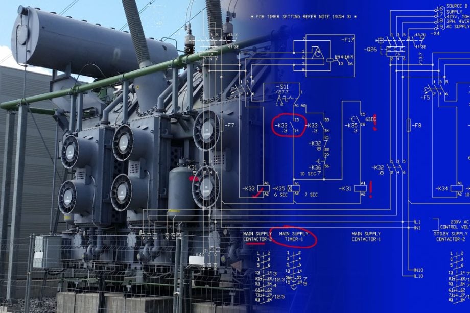
First of all, all transformer drawings should be properly ‘scaled‘. They can be either in first angle or third angle projection. Angle of projection must be mentioned in drawing. Preferred projection is First Angle Projection. Title block should contain customer reference (Customer name, PO/LOI number), Transformer MVA rating and voltage.
Regarding the drawing format, all drawings may be either in A3 or A4 size for easier up-keeping. Transformer drawings should also be submitted in soft form, such as CD or flash memory.
Figure 1 – An example of a power transformer drawing (click to zoom)
3. Essential Information Needed in Drawings
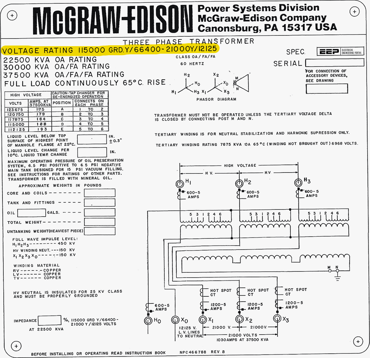
3.1 Rating & Diagram Plate
Rating & Diagram Plate drawing must be in line with the recommendations in related IEC standard. Plate can be made in one part or two. In case of two plates, cross reference should be given in both sheets. You should keep blank columns to fill after testing for % Impedance, measured losses, weight schedule and oil volume for first filling at site.
Weight schedule should contain the following information:
- Core – coil assembly weight
- Tank & fittings weight
- Oil weight
- Total Weight,
- Transport weight,
- Net copper weight,
- Net silicon steel weight,
- Net mild steel weight, and
- Type, grade and standard of oil.
Transport weight can be either oil filled or gas filled (Dry Air or Nitrogen) depending on transport limitations & road route survey. Hence, it can be indicated as Transport Weight (with oil or without oil).
Provision of special accessories connected to windings, zinc-oxide elements across regulating winding, tie-in-resistor in tap changer, external neutral grounding resistors etc. must be provided.
In case air cell is provided in conservator, you should add a note “Conservator is fitted with an air cell”. CT details like ratio, accuracy class, burden, Knee point etc. must be provided. § Rating Plate Drawing should be in the language required by Contractor.
Figure 2 – Transformer nameplate information
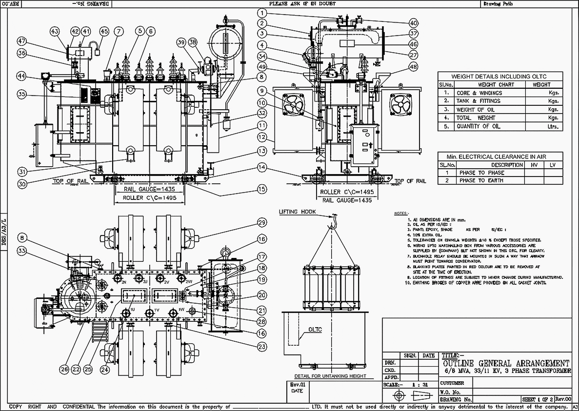
3.2 General Arrangement Drawing
- All accessories & fittings should be numbered with standard logic in line with related IEC standard, so that same number can be used for identical items.
- Approximate Weight & Oil quantity schedule (Weight of core-coil assembly, tank & fittings, weight & volume of oil for first filling, total weight of completely assembled transformer and transport weight with gas or oil filled should be provided as per final design.
- Minimum electrical clearances (Phase–Phase & Phase–Earth) as per related IEC standard must be provided.
- Minimum four views (Plan, Elevation, Right hand side & Left hand side view looking from HV side). 3D views can also be given for additional clarity.
- View showing maximum lifting weight/height of core – coil assembly or upper tank as the case may be and maximum clearance over tank top required for taking out the bushing.
- Tank Earth pad details.
- Core grounding details through terminal board or bushings suitable for 2 kV AC (one minute) isolation test. In case of large transformers (100 MVA and above) the core, core clamp connections must be brought out independently at tank cover in a terminal box and earthed to ground.
- OLTC diverter switch to main tank equalizing details (applicable in case of OLTC only)
- Transformer center line must be the center line of rail gauge.
- Overall dimensions and maximum dimensions on either side of Transformer center line must be indicated.
- Show dimensions up to bushing top terminals from rail level for interface between Transformer and station equipment.
- Show the height and other co-ordinates up to bus duct/SF6 duct and cable pot head mounting with a tolerance of ±10mm
- All dimensions to show the height must be from rail level, until and unless specified in technical requirement.
- Transformer pull out direction must be marked and make sure that there are no obstructions for pulling out transformer from the foundation.
- Make sure the jacking pad position is not fouling with the rail line.
- OLTC conservator must preferably be at same level as main conservator level.
- Buchholz relay must be accessible for inspection, preferably from tank top.
- Accessibility to ladder and from ladder to tank top must be clear from other accessories and pipelines.
- Ladder must be provided with anti-climbing device.
- Positioning of cable box must not be in the path of transformer dragging out path.
- It is preferable to mount the coolers on the transformer tank instead of separate mounting.
- Dial of magnetic oil level indicator must be visible from the ground.
- Provision must be made on tank cover for fixing safety barriers.
- If air cell is provided in the conservator, air cell failure indication (by air operated relay or oil sight window) must be provided.
- Upper filter and sampling valves must be accessible from ground level. All valves must be provided with identification labels.
- Rating and diagram plate must be visible and near to OLTC driving mechanism. Marshalling box with indicators must be near to it. Dials of all indicating and protection meters must be visible clearly when viewed from the front of transformers.
Following notes and cross reference document numbers must be given.
- Tolerance on weights and dimensions must be within ± 5% unless marked separately.
- External painting system and shade number e.g. shade number (631 of IS:5), epoxy zinc primer + epoxy intermediate + polyurethane paint (preferred system)
- Document number of Bill of Material for cross reference, if accessories are listed up in a separate drawing
- Drawing numbers of Rating & diagram plate, Valve schedule plate, Foundation plan, Transport dimension and bushings.
- Design features generally meet the statutory, regulatory and safety requirements in terms of earthing arrangement, danger / warning labels, air clearances and provision of pressure relief device, gas operated relay and earthquake withstand clamping to foundation.
- Terminal Connector must be arranged by Customer.
Recommended – Distribution transformer guide: Installation, commissioning, operation and maintenance hints
Distribution transformer guide: Installation, commissioning, operation and maintenance hints
3.3 List of Accessories
- List of Accessories can be on separate sheets. GA drawing number must be given as a cross reference.
- Description, Make and quantity of all accessories must be given.
- Items disassembled for transport must be indicated clearly.
- Mercury filled actuating switches must be avoided in all accessories.
Further Study – Often incorrectly specified and ordered: Power transformer fittings and accessories
Often incorrectly specified and ordered: Power transformer fittings and accessories
3.4 Bill of Materials (BOM)
- Bill of materials should be on separate sheets. One or more A4/A3 sheets can be used. GA drawing number must be given as a cross reference.
- Description, Make and quantity of all accessories must be given.
3.5 Transformer Foundation Plan
- Constructional and fixing details of foundation bolt.
- Foundation bolts must be under the scope of transformer supplier. Grouting of bolt must be done at the time of transformer erection for matching purpose.
- Load on each support must be clearly stated.
- Transformer Pull out direction must be marked in line with GA
- Foundation bolt must be part of BOM.
- Rail gauge must be marked in foundation drawing.
- Anti-earthquake features in foundation/clamping (in case of transformers for seismic zones).
Related electrical guides & articles


Edvard Csanyi
Hi, I'm an electrical engineer, programmer and founder of EEP - Electrical Engineering Portal. I worked twelve years at Schneider Electric in the position of technical support for low- and medium-voltage projects and the design of busbar trunking systems.I'm highly specialized in the design of LV/MV switchgear and low-voltage, high-power busbar trunking (<6300A) in substations, commercial buildings and industry facilities. I'm also a professional in AutoCAD programming.
Profile: Edvard Csanyi
