
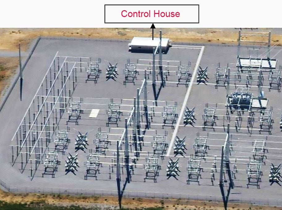
Control house
Nowadays, the control house is one of the main parts of every modern HV switchyard and substation. Why? Simply, because substations have grown in complexity and equipment such as circuit breakers, switch disconnectors, CT, VTs, and others must be controlled, monitored, and protected from some common point in the field.
 Control house at HV/EHV switchyards and substations (construction, layout and functions) - photo credit: eq-house.com
The necessity for supplemental equipment such as protection relays, controls, batteries, communications equipment, and LV distribution equipment also increases. And all that equipment must be placed somewhere in the field.
That’s why the substation needs a control house. In short.
For small distribution substations, this equipment can usually be contained in weatherproof enclosures or control cabinets. For larger substations, separate equipment housing is necessary.
MV and LV switchgear can also be contained within control houses, or this equipment may be contained within weatherproof enclosures dedicated to that purpose.
1. Control house construction
This section discusses general aspects of the control house construction.
1.1 Foundation
The control house foundation typically consists of a spread footing with either masonry blocks or cast-in place walls. The footing is designed for an allowable bearing capacity based on soil data. If soil data is not available, a maximum bearing of 48 kPa can be used.
The footings are installed below frost depth and in accordance with local building codes and practices.
Damp-proofing of foundation walls is desirable, especially if concrete block is used. If a basement level is constructed, damp-proofing should be provided.
Footing drains are usually provided when a basement level is constructed. All foundation walls should be insulated with a 5.1-cm (2-inch) thickness of rigid insulation for energy conservation.
It is preferable to install the insulation on the inside of the walls, although the outside is acceptable.
1.2 Floor
The control house floor is typically a floating concrete slab 12 to 16 cm thick reinforced with welded wire fabric, deformed steel bars, or a combination of both.
The finished floor elevation is usually 10 to 20 cm above the finished grade outside the control house.
The base beneath the floor slab should be 10-12 cm of compacted sand or gravel, thoroughly mixed and compacted sand or gravel, or thoroughly mixed and compacted natural soil. A 0.15 mm thick plastic film vapor barrier should be installed between the floor slab and the base.
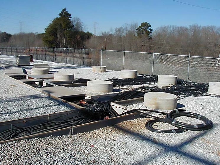
The method for cable routing in the control house has to be considered before finalization of the floor slab design. Cable trenches can be formed into the floor slab, or false floors can be installed providing access to large areas below the finished floor.
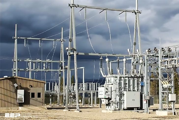
1.3 Control house structure
The control house structure must be constructed from fire-resistant, low-maintenance building materials. Most control houses presently being designed and constructed are of the pre-engineered metal or masonry block type.
Figure 3 show example of control building structure type.
Masonry buildings constructed of block masonry are most economical when masonry module dimensions are used to size the building and the building openings.
Two types of roof systems are commonly used for masonry buildings: pre-cast, pre-stressed concrete panels; and steel joists and steel decks. A sloping roof is recommended for both systems and can be obtained by pitching the roof deck or installing tapered roof insulation.
The roof membrane has to be compatible with the slope. For the slopes of 8.3 cm/m (1 in./ft) and less, built-up pitch and slab is commonly used. For greater slopes, gravel is used.
The control house should be equipped with at least one double door, possibly with a removable transom, conveniently located to facilitate equipment entry and removal. In certain circumstances a second exit needs to be installed in the control house.
The National Electrical Safety Code (NESC) states:
If the plan of the room or space and the character and arrangement of equipment are such that an accident would be likely to close or make inaccessible a single exit, a second exit shall be provided.
The National Electrical Code (NEC) also defines specific requirements for a second exit. The doors should include locking devices, astragals to prevent water from entering, and adequate weatherstripping and hardware to permit a rapid exit from the control house.
Locate and mark adequate fire-extinguishing equipment in the control house. Windows can be provided, if desired, in office and lavatory areas. Battery rooms and control and metering areas do not need windows.
Consider adequate methods for building insulation. These methods include use of insulated wall panels, ceiling insulation, storm doors, and windows, and weatherstripping around all openings.
Metal buildings are shop painted and require only minor field touch-up after erection. Masonry buildings may be left unpainted or may be painted with portland cement or latex paint. Tint all prime coats to match the finished coat.
2. Control house layout
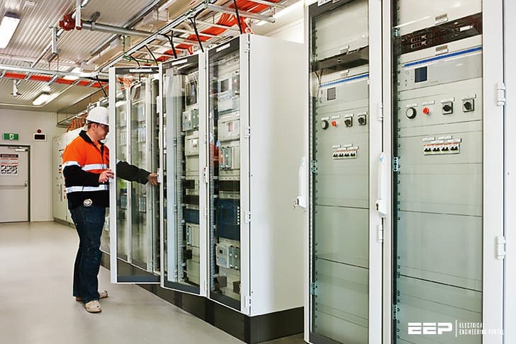
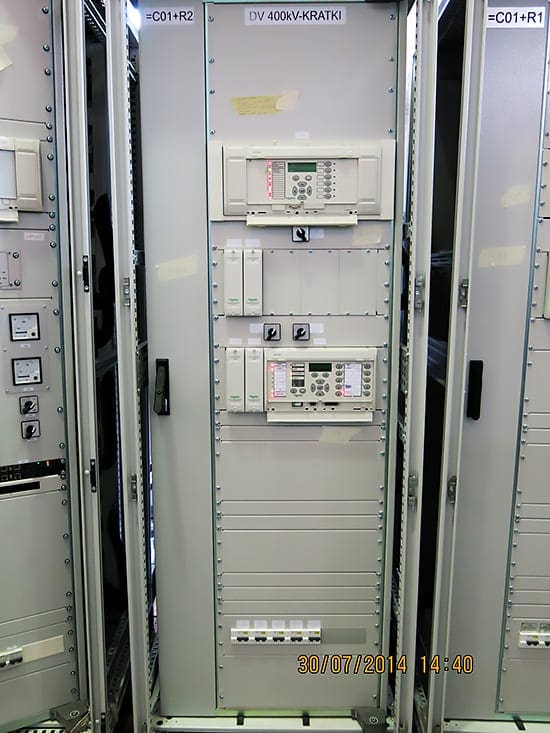
2.1 Control and Relay protection Panels
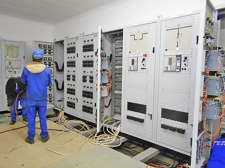
Most protection relaying, metering, and control equipment is mounted on fabricated control and relay panels installed within the control house. A variety of panel types is available to suit individual requirements.
Figures 4, 5 and 6 show examples of various panel layouts.
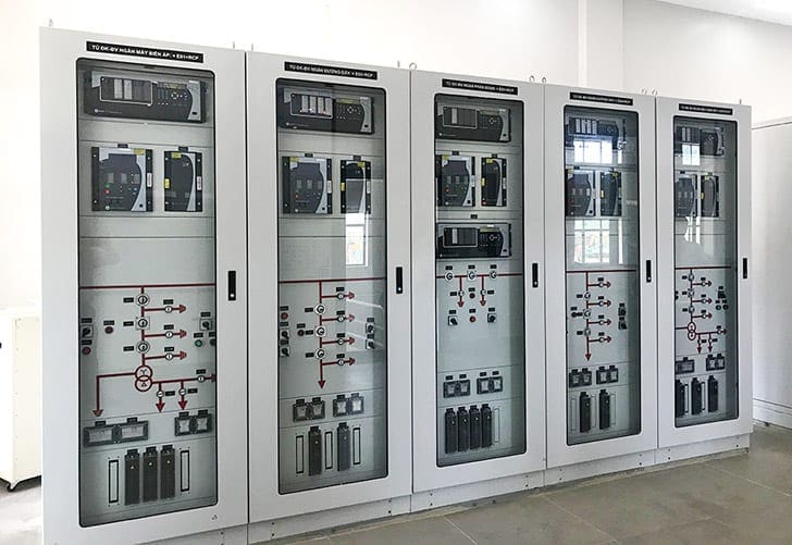
Single vertical panels can be used, particularly for distribution circuits where space requirements are minimal. The relaying, metering, and control equipment can all be mounted on one panel, allocating a separate panel for each circuit. In some instances, two circuits may share the same panel.
Double or duplex panels are commonly used for higher voltage circuits, necessitating additional space for equipment mounting. Normally, these panels are arranged in two parallel rows with the panel backs facing each other. In this configuration, operating, instrumentation, and control equipment for a circuit is installed on the front of one panel, and the corresponding relaying equipment for the same circuit is installed on the front of the panel directly to the rear.
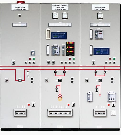
In some instances, two circuits may share the same control and relaying panels.
Some equipment such as static relaying systems and communications equipment is available mounted in racks. Consequently, separate relay and/or control panels are not required for this equipment.
The trend is toward more compact equipment arrangements that often reduce overall control house size.
Individual three-phase microprocessor relays can replace three single-phase electromechanical relays and associated voltage, current, and power meters, all in one case.
Compact relay and programmable logic controller designs can be mounted on 48.26-cm (19-inch) racks.
To facilitate operation, panels are located in an arrangement that conforms as closely as possible to the actual equipment and circuit layout in the substation yard. To assist in circuit location and operation, mimic buses are sometimes used on the control panels, particularly for large complex substations.
The mimic buses identify the bus and circuit arrangements.
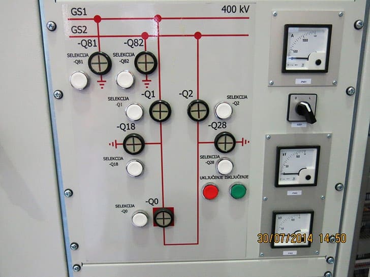
Mimic buses may be implemented on screens viewed from a PC monitor. When practical, position meters at eye level and switches at a convenient operating level. Locate recording meters for ease of viewing and chart replacement.
Provide ample space for relay installation, removal, operation, and testing. Panel construction can include removable front plates for device mounting.
Panels may also include 19-inch rack mounting facilities. Many of the newer relays and items of accessory equipment are designed to fit into 19-inch racks. Cover plates may cover space reserved for future use. In this way, only a new predrilled plate is required when changing out a device or modifying the configuration.
Cutting, drilling, or covering openings in the panels is eliminated.
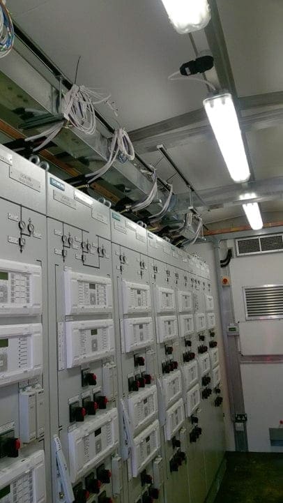
Panel wiring is accomplished on the backs of the panels. Devices are interconnected and wired to terminal blocks, as required, for operation and connection to devices on other panels.
Panels can include small sections perpendicular to the main section at each end for installation of terminal blocks, fuse blocks, or small auxiliary devices.
Cable connections from the equipment in the substation yard can be made directly to terminal blocks mounted on the panels or to strategically placed terminal cabinets. Interconnections between the terminal cabinets and the panels can then be made with single conductor wire.
Anchor panels to the floor in such a way as to facilitate relocation to coincide with yard equipment and circuit relocations.
Panel arrangement in the control house should permit ready accessibility to the backs of the panels. Some vendors of pre-engineered buildings can provide completely wired and tested control and relay panels and auxiliary AC/DC power systems as part of the building package.
In this way, the entire panel line-up can be witness-tested in the factory. The complete building system is shipped to the site, fully tested. Only the external wiring from the building to the outdoor equipment has to be field-installed.
