
Why use a Control Power Transformer?
The motor branch circuit is usually a segment of a larger electrical distribution network in an industrial plant. The motor circuit supplies the required power to the various control devices in order for them to operate. In some cases, the various control devices are operated at the same voltage as the motor.
 Using control power transformer for motor control circuits
Sometimes, the voltage required to operate the motor is too high to safely operate the control circuit, particularly in regards to personnel safety.
Connected with the Primary winding to the Power circuit – Secondary winding to the Control Circuit
A typical control transformer is shown in Figure 1 below. It consists of two separate coils of wire (windings) placed adjacent to each other on a common iron core. Note that the primary winding is connected to the power source. The secondary winding is connected to the control circuit. The purpose of the transformer is to transfer electric power from the primary circuit to the secondary circuit.
The transformer either reduces (steps down) or increases (steps up) the voltage to match the requirements of the control circuit.

Magnetic field from primary winding induces voltage in the secondary winding.
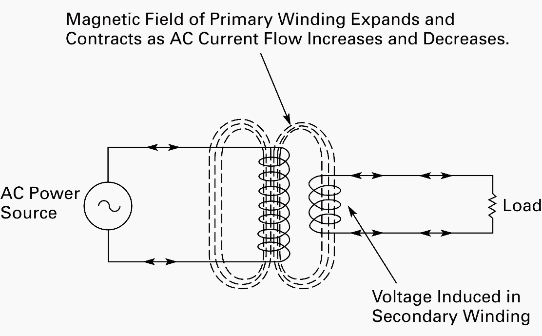
Applying AC voltage to the primary winding of the transformer causes alternating current (AC) to flow in the winding.
This produces a magnetic field that extends outside the winding, in the shape of concentric loops as shown in Figure 2. The magnetic field fluctuates as the AC changes direction. These magnetic lines cut across the conductors of the secondary winding and induce a voltage.
Voltages based on number of turns on both windings.
The relationship of the voltage across the primary to the voltage across the secondary is in direct proportion to the number of turns on both windings. For example, 100 turns on the primary, and 10 turns on the secondary, is a 10 to 1 ratio. If the primary is 500 volts, we will get 50 volts at the secondary.
This is referred to as a Step-Down transformer.
A transformer with the reverse proportion of more turns on the secondary winding than on the primary is called a StepUp transformer. It will increase the voltage according to the ratio of turns.
Primary connects to the power circuit — Secondary connects to the control circuit.
The schematic symbol for the transformer is represented by two groups of “scallops” facing each other. These represent the primary and the secondary windings. The winding with the higher number of turns should be shown to have more scallops than the other to identify it as either a step-down or step-up transformer.
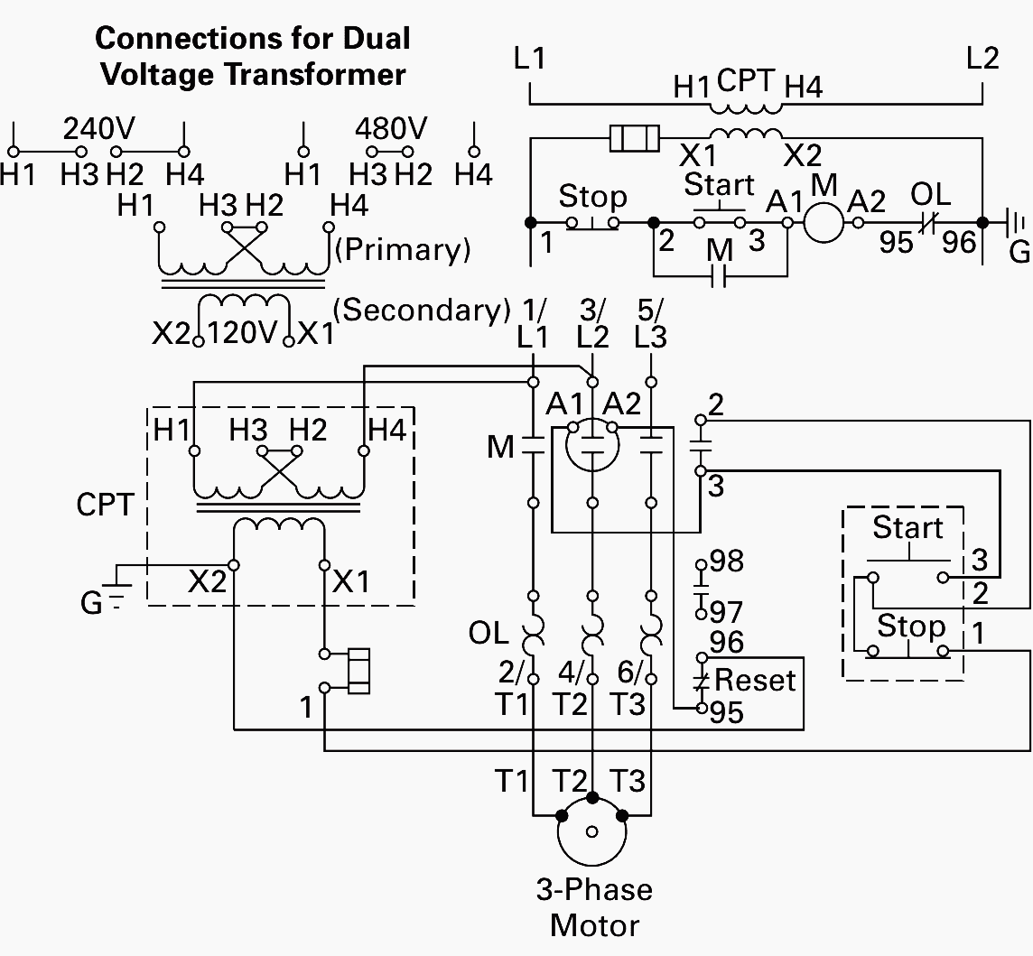
Figure 3 shows a basic control circuit with a step-down transformer added. Note that the main motor circuit operates at 480V, while the control circuit is at 120V.
The primary winding of the transformer is connected to two phases of the power circuit. The secondary winding is connected to the control circuit.
Control Circuit Wiring of CPTs
Magnet Coil and Pilot Lights rated for same voltage as Secondary of Transformer.
When you are installing a Control Power Transformer into a starter, you must be sure that the magnet coil is rated for the same voltage as the secondary of the transformer. In addition, any pilot lights in this circuit must have the same voltage as the secondary.
Dual Voltage units shipped with connections made for the higher voltage.
When you are using a Control Power Transformer with a dual voltage primary, check the transformer connections to be sure that they match the voltage of your power source.
Remove wire “C”, if supplied, from starter’s control circuit. As discussed earlier in this booklet, if wire “C” is supplied on the starter (magnet coil voltages greater than 120V), you must remove it. This will convert the starter from Common Control to Separate Control.
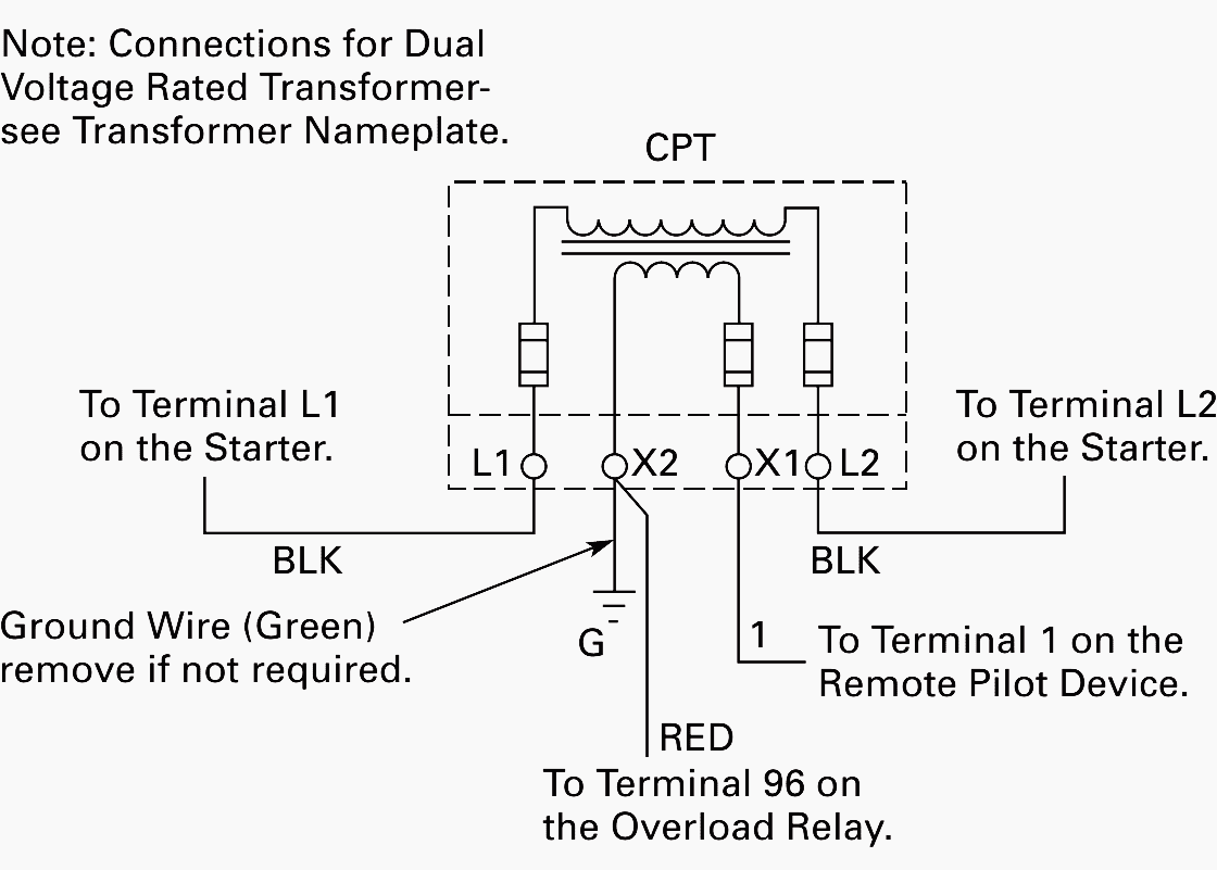
The leads from the primary of the transformer are connected to L1 and L2 on the starter. In this way, the primary of the transformer is supplied with the same voltage as the power/motor circuit of the starter. The leads from the secondary of the transformer are connected to Terminal 1 of the remote pilot device, and terminal 96 on the Freedom Series overload relay (see Figure 4 above)
Eaton Cutler-Hammer Installing A Control Power Transformer in Enclosed Controls
Reference // Basic Wiring for Motor Contol by EATON


Good day, Edvard! Your knowledge about the Wiring of control power transformer for motor control circuits is really informative. You have great knowledge of power transformers. I am happy to be on your blog. Keep going.
Design test bench 800KW pump test bench low harmonic vfd 415V i/p to step up transformer 6.6kv and 3.3kv. Wants to know rating of transformer and terminal connection of transformer to motor pump
Am filling very happy, but how I which, l could be in this company.
Another reason for the step down xfmr is not only safety of personnel and pilot lights, atypical motor starters are connected to an additional remote start EMS or BCMS relays.
The smaller ice cube relays, typically switch the control circuit on and off at a lower voltage i.e. 120 vac here in the U.S.A. Controlled by a 24 vac control circuit. Thus the remote start safety aspect.