
Estimated Study Time: 11 minutes
Controlling reactive power
Most compensation banks are controlled stepwise. For this purpose it is essential to ‘know’ when it is allowed to (de)activate a capacitor step by the power factor relay (controller). The so-called C/k value is calculated by the step size C divided by the ratio k of the current transformer.
 How To Control Reactive Power With Multiple Incomers In Larger Electrical Plants (on photo: Fraunhofer IISB’s building complex with advanced power monitoring system by Siemens; credit: Siemens)
It is clear that a capacitor with, for instance, 50 kvar may not be switched in if the power factor relay measures a deviation of just 10 kvar reactive power with regard to the preadjusted power factor target.
This technical article explains two ways of controlling reactive power in plants with with multiple incomers:
- Measuring by Means of Summation Current Transformer
- Parallel Operation of Compensation Banks for Each Incoming Supply
- Summary
1. Measuring by Means of Summation Current Transformer
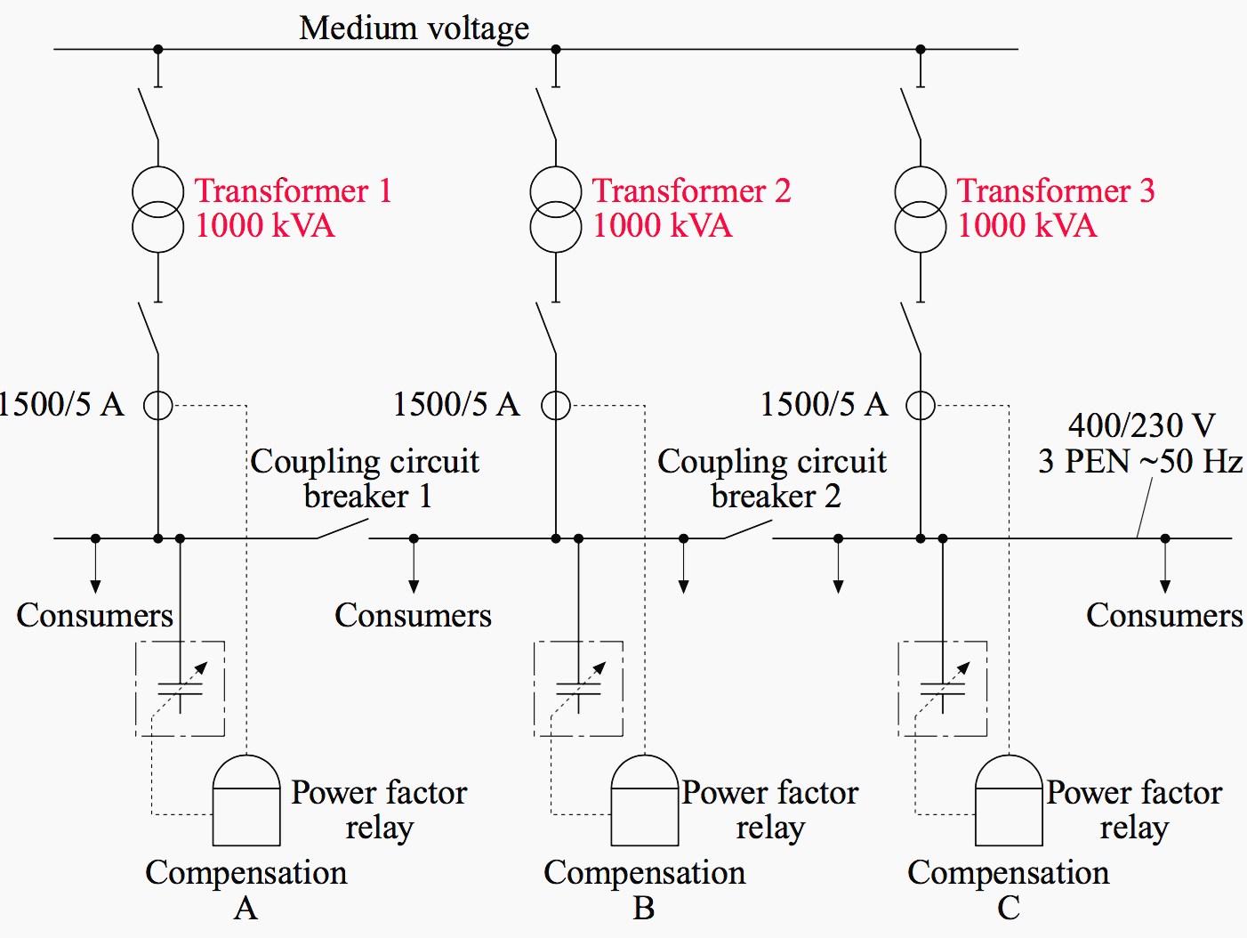
Larger electrical plants have multiple feed-ins with two or more power transformers usually working in parallel. Regarding the control of reactive power, there are two solutions possible.
This output is wired to the current path of the power factor relay controlling a 12-step central compensation bank of 600 kvar.

The method has a big disadvantage: for proper control of reactive power it is necessary to keep the two coupling circuit breakers 1 and 2 closed all the time! In case of any short circuit, all three power transformers generate a very high power as a rule.
Suppose coupling circuit breaker 1 is opened – then the power factor relay is not able to compensate the reactive power of consumers connected to the busbar to the left. However, the relay notes a higher request for capacitors to be switched in.
The third disadvantage is that the power factor relay is not able to ‘see’ in which area reactive power arises, due to the summation current transformer and the central-type compensation connected to the busbar in the middle. Despite this, it is essential to discuss how to calculate the C/k value for correct adjustment.
For this purpose Equation 1 is used:

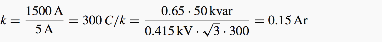
Factor k is to be determined separately:

The first term symbolizes the total ratio of the three current transformers, and the second, symbolizing the summation transformer to be multiplied, results in a very high total ratio of k = 900. It is then necessary to check whether the relay’s minimum sensibility of 1% will not be undersized.
Finally the C/k value is to be calculated according to Equation 1:

Suppose a fourth incoming supply with an additional power transformer of 1000 kVA increases the total ratio referring to four current transformers to be summarized up to k = 1200 and the C/k value decreases down to 0.038 approximately.
This value decreases the 1% level distinctly.
There would be only the possibility of varying the factor of 0.65 up to 0.85 or, in another calculation, to show at which percentage of the step size (50 kvar) a power factor relay with fully automatic C/k adaption would start to control:
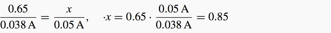
The relay would re-energize the capacitor at a level of 85% referring to 50 kvar, or 42.5 kvar only. Proper control of the capacitors is no longer guaranteed due to the tolerances of the relay and the capacitor as well.
Regarding factor k, it does not matter whether all power transformers are in operation or not. Factor k is just a characterizing constant of the entire electrical plant.
This method of controlling reactive power has some disadvantages, as noted above. To install individual compensation banks for each incoming supply is much more suitable, as described in the following paragraphs.
2. Parallel Operation of Compensation Banks for Each Incoming Supply
Referring to Figure 2, the advantages can be seen at once. Control of reactive power runs individually for each incoming supply with the help of its own compensation bank, each controlled by an automatic reactive power controller.
It does not matter if the position of the coupling circuit breakers 1 and 2 is open or closed. If they are open, the compensation banks operate individually. If they are closed, one encounters the parallel operation, to be discussed next. All three power factor relays working in parallel are preset to the identical power factor target between each other.
The C/k calculation from Equation 1 again is simple as no summation current transformer must be considered.
Thus the ratio of the current transformer amounts to:
This C/k value is to be preset at each relay with manual or half-automatic C/k adaption identically in the case of open coupling circuit breakers. But what is the situation with closed coupling circuit breakers?
The step size of 50 kvar is only one-third measured by the current transformers, supposing the same impedance voltage at the power transformers operating in parallel.
Thus the best solution would be to use power factor relays with the feature of ‘full automatic C/k adaption’.
They always register the so-called compensation effect for each step independently of the position of the coupling circuit breakers 1 and 2. Even if breaker 2 is open and 1 is closed, the current transformer of compensation bank C registers the full size of the capacitor, but the current transformers of compensation banks A and B only half the size.
It is not necessary to discuss the disadvantages of power factor relays with manual or half-automatic C/k adaption further.
During the installation of large electrical plants with currents of more than 1000 A approximately occurring attention should strictly be paid that, for example, cables from the power transformers to the busbars are of the same length in order to ensure symmetrical load distribution.
Another situation it is essential to mention is the case when one power transformer, for example no. 3, is out of operation due to maintenance and, provided that the coupling circuit breakers are closed of course, that the power factor relay of compensation C is energized but does not get any signal from the current transformer.
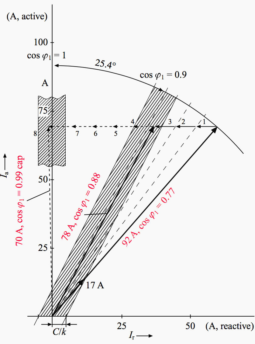
With regard to Figure 3 there is no vector existing that exceeds the C/k threshold level. Older relays would ‘stand by’ with the number of capacitors switched in as before. They would not be able to establish control until maintenance is finished.
Not all brands of power factor relays have the capability to disconnect the capacitor(s) after a defined measurement time of ‘no current’ or ‘I = 0’ is displayed. Thus it is essential to get information on this from the manufacturer.
To sum up
Summarizing, it is best to focus on the described method in preference to the method of Section 11.6.1 as there are several advantages:
- Control of reactive power independently of the position of the coupling circuit breaker.
- Possibility to limit the power in case of a short circuit.
- De-centralized compensation enabling location much closer to consumers of reactive power.
Reference // Reactive power compensation by Wolfgang Hofmann, Jurgen Schlabbach and Wolfgang Just (Purchase hardcover from Amazon)
Related electrical guides & articles


Edvard Csanyi
Hi, I'm an electrical engineer, programmer and founder of EEP - Electrical Engineering Portal. I worked twelve years at Schneider Electric in the position of technical support for low- and medium-voltage projects and the design of busbar trunking systems.I'm highly specialized in the design of LV/MV switchgear and low-voltage, high-power busbar trunking (<6300A) in substations, commercial buildings and industry facilities. I'm also a professional in AutoCAD programming.
Profile: Edvard Csanyi

Your article is very useful to me.
thank you so much
very useful articles
I am a mechanical engineer and I have built three wind farms of 50 towers as construction manager. Of course, your system shown would be for 50 sources of power to the MV; I heard a lot about reactive power, but did not know what was behind it until I read your explanation. Thanks Edvard,
Remi Laforest
Steelman Industries builds a system that works on the third concept in your article for industrial customers and it works well. Proper attention and maintenance is required for continuous service when needed to prolong equipment life while reducing plant cost.
Your work is very useful to me.
You are doing a wonderful job. Your is very useful to me.