
Estimated Study Time: 8 minutes
Pushing loads over design limitations
As you already know, cooling is really essential for long transformer life. Most transformers are designed for 55°C or 65°C rise. Using newer insulations such as Nomex, temperatures of 95°C and higher can be achieved.
These temperatures can only be maintained if the transformer operating conditions do not exceed the design limitations.
Unfortunately, in today’s operating environment, most end users are pushing loads well past nameplate design limitations resulting in increased winding temperatures. These temperatures are primarily due to increased losses such as I2R.
Increased heating plays a major effect on the degradation of insulation quality and drastically diminishes its life expectancy. Here the standard 10°C rule of thumb still applies for insulation half life.
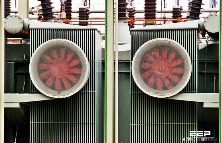
Transformers are either self cooled through natural oil convection and rated ONAN (Figure 1) or fan cooled and rated ONAF Figures 2 and 3. In most extreme cases, forced oil or forced oil over water cooling with a rating of OFAF or OFWF (Figure 7) are used.
In each case, it is extremely important that proper temperature transfer takes place. The design of the transformer relies on a specific heat transfer between the windings, oil and the radiator or cooler for heat extraction. Any increase in heat generation or any heat transfer reduction results in higher winding temperatures and shorter insulation life. Additionally, the dielectric fluid is degraded and will be covered in a later section.
")
 using natural oil convection (bottom mount up draft)")
Bottom mount fans blow air across the total length of the cooler or radiator but have higher motor failure due to water entrance around the shaft seal. The use of totally enclosed, nonvented motors with high quality shaft seals do, however, increase motor life. Inspection of these motors should be made monthly.
Open frame motors are not recommended in any case due to higher failure rates caused by environmental considerations.
")
Typically one fan failure does not cause serious problems but does result in an overall temperature increase for the transformer especially if it is overloaded as can be seen in infrared Figure 4. Fans typically fail in batches. They are manufactured at the same time and operate in the same environment.
Observation of one failure should be an indicator that others may be ready to fail as well leaving the transformer in danger of over temperature.

Figure 5 shows loss of cooling in some radiators due to concrete pad settling tilting the transformer. This can, in some cases, be corrected by increasing the oil level in the main tank to a level permitting oil flow through the radiators.
Care should be taken to not overfill and create a problem due to oil expansion that takes place during overheating.

In Figure 6 all of the oil valves to the radiators are higher than the oil which prevents oil circulation. Low oil level can be a result of leaks or failure to be adequately filled when last serviced. One last issue causing the same consequence happens if the upper butterfly valves to the radiators are turned off during maintenance and not turned back on which prevents oil flow.
A simple thermography test will reveal this life-robbing problem.

Forced oil pumping systems FOA/ FOW (Figure 7) provide for high flow rates through radiators and the transformer providing maximum heat transfer.

Pump flow rate is hard to measure and typically uses a small vane gage located in the piping indicating pump ON or OFF activity. Flow indicators are not always ac- curate. Many times during maintenance a gage is found to be stuck and does not truly indicate flow.
Pumps, themselves create their own set of failure modes in a transformer. Built to tight tolerances, they do not tolerate loose bearings or bushings. As they age, bearings, bushings or thrust washers wear and can cause impeller drag on the pump housings (Figures 8 and 9). This causes large deposits of metal filings to be deposited in the transformer windings and eventually causes insulation failure as they vibrate at operating frequency and wear in.


Ultrasonic inspection for bearing wear is an excellent test and can be performed at anytime as long as the pump is running as shown in Figure 10.

Reference: Transformer Testing — Are You Missing the Test Point? by Rick Youngblood American Electrical Testing Co.
Related electrical guides & articles


Edvard Csanyi
Hi, I'm an electrical engineer, programmer and founder of EEP - Electrical Engineering Portal. I worked twelve years at Schneider Electric in the position of technical support for low- and medium-voltage projects and the design of busbar trunking systems.I'm highly specialized in the design of LV/MV switchgear and low-voltage, high-power busbar trunking (<6300A) in substations, commercial buildings and industry facilities. I'm also a professional in AutoCAD programming.
Profile: Edvard Csanyi

motor, compressors and transformers, breakers
Envirnonmental testing (climate chamber testing) of such prototypes can be usefull with repect to this manner as simulations can be time consuming and complex. At OWI-Lab in Belgium we have set-up one of the largest climate chamber that can cope with more than 150 ton components to perform extrme hot and cold temperature testing on transformers: http://blog.sirris.be/blog/multi-mw-electrical-systems-wind-turbines-tested-owi-labs-environmental-test-facility
I find this information very useful in my consultancy work since I need to brush up my knowledge every now and then.
Kindly suggest the best equipment for undertaking thermographic scannig and ultra sonic checks in HV substations