
Estimated Study Time: 11 minutes
Relaying and control coordination
The installation of a dedicated substation to serve a plant actually involves an interface between the utility and the plant. Close coordination between utility and plant personnel is essential so that relaying, control and other related requirements are identified and proper responsibilities assigned.
 Coordinating study in protection of utility supply line, transformer & plant main bus/feeder
This may include requirements that the plant provide equipment or space for the utility’s relaying, control, metering, data acquisition, and other related equipment.
There are three general areas where protection requirements must be coordinated to ensure a safe and reliable system:
1. Utility supply line protection
Typically, line faults may be detected and isolated using overcurrent, distance, pilot wire, or differential relaying protective techniques.
Several factors influence the choice of line protection, including:
- Circuit type (e.g., underground cable, overhead line, single circuit, parallel circuit, multi-terminal lines, etc.) and
- Line’s function and importance (e.g., impact on service continuity and the amount of time needed to detect and isolate faults).
It is important to understand that the utility scheme used may well impact plant operations. Any conflicts in objectives between the utility protective scheme and maintenance of critical plant operations should be resolved.
2. Transformer protection
The protection schemes for transformers depend on several factors, including system configuration, method of grounding, speed, coordination, operation, cost, etc. Some of the more commonly used protective schemes for industrial substation transformers are shown in figures 1 through 4.
Figure 1 shows how a primary breaker can be used for transformer protection.
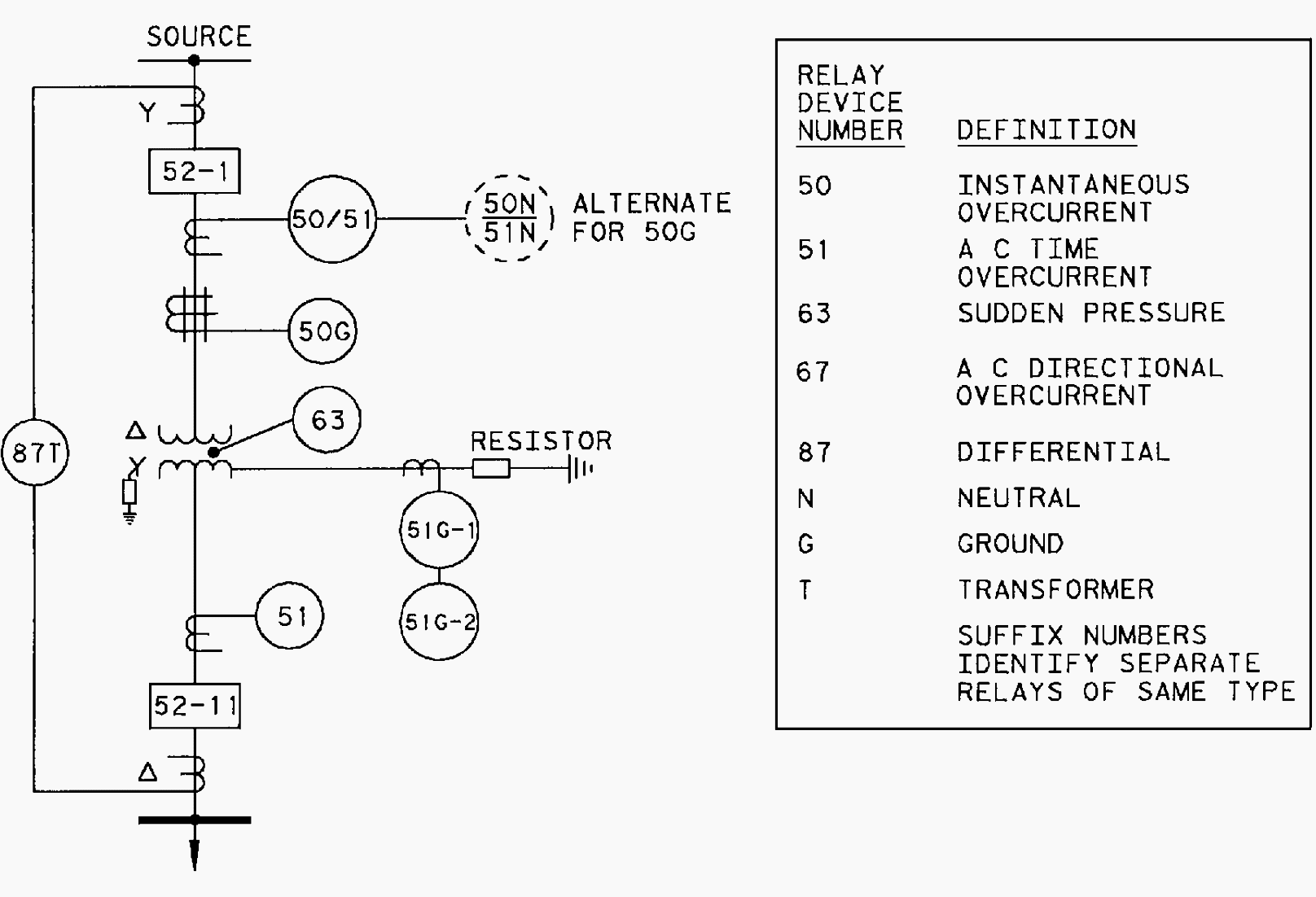
The basic protection is provided by the 87T transformer differential relays. Device 50/51, overcurrent relay with instantaneous unit, provides primary protection for phase faults; either Device 50G or 50N/51N can be used as backup protection for ground faults.
Transformer overload, low-voltage bus, and feeder backup protection is provided by Device 51 on the secondary side.
Since the low-voltage side is resistance-grounded, a ground relay (51G-1) should be used to trip Breaker 52-1 for low-side ground faults between the transformer and the secondary breaker and for resistor thermal protection.
Devices 50/51, 51, 51G-1, 50G, and 51G-2 require coordination to provide zones of protection, which will aid in fault location.
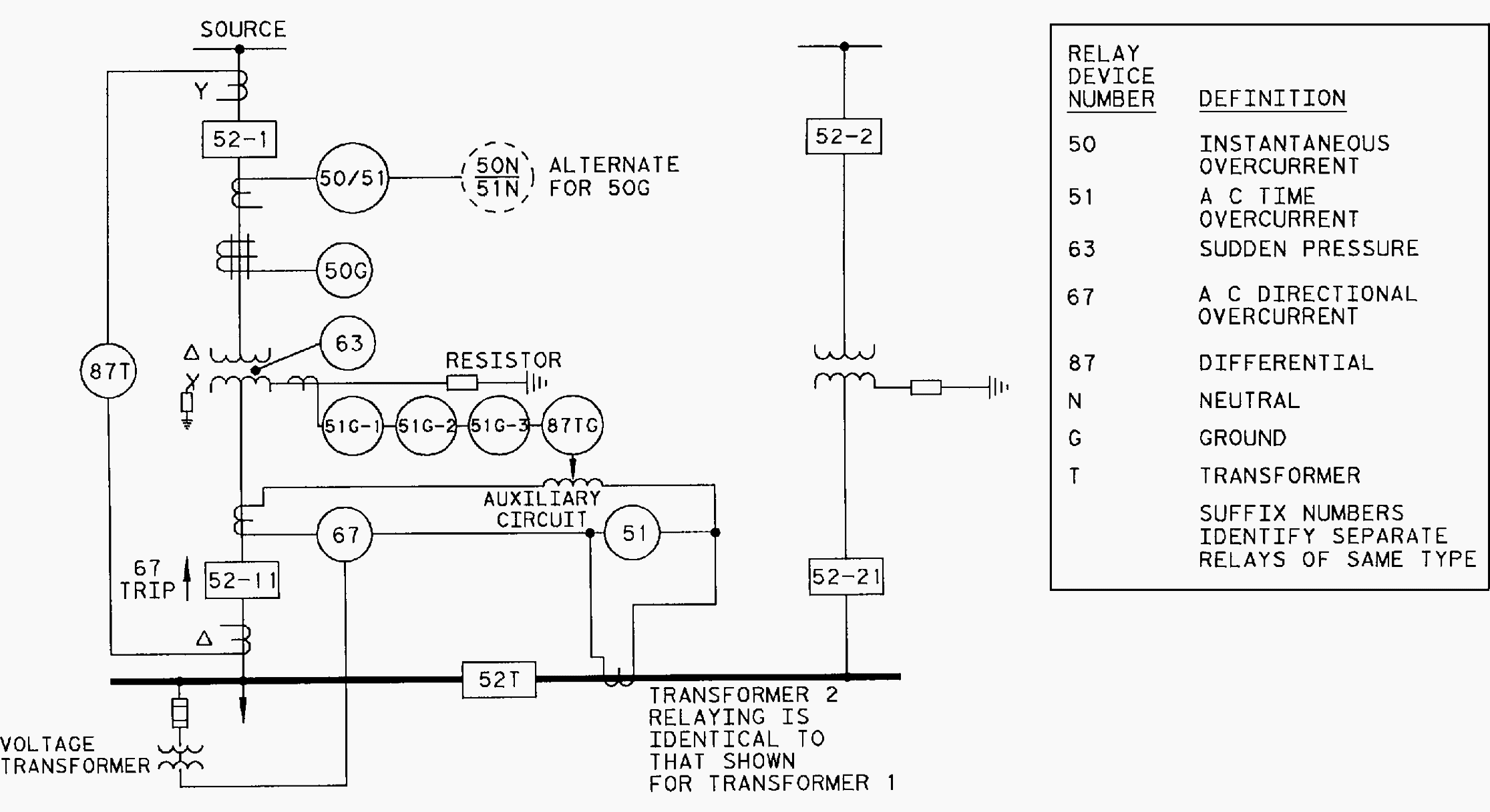
When a normally closed secondary bus tie is used for paralleled transformer protection (figure 2 above), there are several differences from the primary breaker scheme shown in Figure 1.
The trip sequence of these three ground relays is as follows:
- 51G-3 Trips 52T,
- 51G-2 Trips 52-11,
- 51G-1 Trips 52-1, and
- 87TG Trips 52-1 and 52-11.
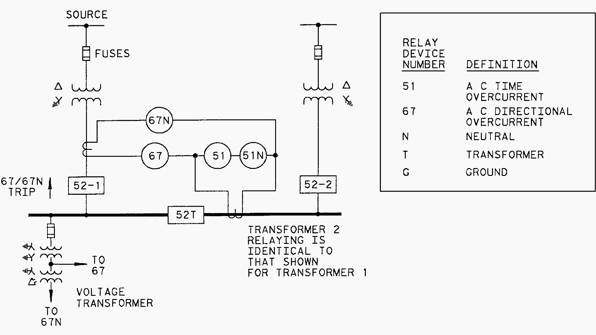
Device 67 provides directional overcurrent protection.
If the transformer size does not warrant the basic schemes described above, the schemes shown in figures 3 and 4 may be used. Here, fuses provide the primary fault protection. Solid grounding will assure sufficient primary phase fault current to operate the fuses for most secondary ground faults.
In cases where secondary ground faults do not produce enough fault current to blow primary fuses, a 51G relay may be used to trip a high-speed ground switch, as shown in Figure 3.
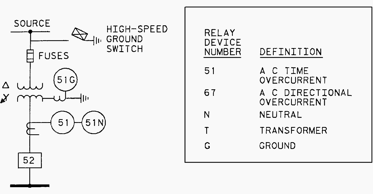
The opening of a single primary fuse will result in single phasing of the transformer secondary system. This may be difficult to detect, particularly at light loads, and appropriate precautionary measures should be taken. If the utility source is grounded and there is a power source on the secondary side, a ground fault on the incoming line will be interrupted by the utility breaker.
The secondary breaker, however, will not be relayed open because no ground-fault current will flow through the delta primary transformer connection.
Failure of the secondary breaker to open can result in hazards to personnel, possible damaging transient overvoltages produced by an arcing-type fault, and prevention of automatic reclosing of the utility breakers.
Note that certain fusible switches are available that will automatically open all three phases should a fuse melt on single-phase.
In some cases, it is appropriate to specify Type 60, voltage or current balance/ negative sequence, relay protection on the secondary of transformers with fused primaries to provide single-phase protection.
When a normally open bus tie is used, as in Figure 2 and Figure 4, Devices 67 and 67N are not required.
Where transformers with no high-side breakers are applied as part of a line section, transfer tripping or the application of high-speed ground switches or circuit switchers operated by the transformer protective relays may be used for transformer protection.
For this type of application, the remote ground relays can be set to operate for 100% of the line and not overreach the low-side bus at the transformer location.
The use of high-speed ground switches is not desirable where power quality is a major concern.
3. Plant main bus and feeder protection
Plant main bus protection may be provided by overcurrent or differential protection schemes. Overcurrent protection should be coordinated with that provided for transformer protection.
When applied for bus protection, the partial differential scheme is most commonly used for protection of plant main buses. In this scheme, only the source circuits are differentially connected, using an overcurrent relay with time delay. The relays protecting the feeders or circuits are not in the differential.
Essentially, this arrangement combines time-delay bus protection with feeder backup protection.
Where some or all of the feeder circuits have current-limiting reactors, a partial-differential circuit is used with distance-type relays. These distance-type relays are set into, but not through, the reactor impedance. The reactor impedance is used to select between faults on the bus and external faults on the feeders. The scheme is both fast and sensitive.
Prior to specification of equipment, short-circuit and protective-device coordination studies must be performed.
The coordination effort is intended to produce a complete record of protective-device ratings and settings and suitable time–current curves, etc., to ensure proper and coordinated operation of all protective devices with the utility supply and for plant system faults.
Source // Recommended Practice for Electric Power Distribution for Industrial Plants by IEEE
Related electrical guides & articles


Edvard Csanyi
Hi, I'm an electrical engineer, programmer and founder of EEP - Electrical Engineering Portal. I worked twelve years at Schneider Electric in the position of technical support for low- and medium-voltage projects and the design of busbar trunking systems.I'm highly specialized in the design of LV/MV switchgear and low-voltage, high-power busbar trunking (<6300A) in substations, commercial buildings and industry facilities. I'm also a professional in AutoCAD programming.
Profile: Edvard Csanyi

YES I WANT TO LEARN ABOUT PROTECTION
Nice information. Very helpful for designing of LT and MV panels.
How about Over voltage relay where it is applicable to protect in the system.
There is no detailed relay coordination and not shown any examples.Relay coordination subject a very biggest chapter kindly arrange one article.
I love this info on the various Electrical component.
From a design perspective, why would a subtractive transformer be a better choice then an additive.
I want to learn more about electrical engineering
Yes I want to more learn about Electrical