
Estimated Study Time: 13 minutes
13 kV distribution feeder
A typical 13 kV feeder of several lines at a distribution substation is shown in Figure 1. This is supplied from a 115 kV line through a 15/20/25 MVA transformer protected by a high-side fuse. Only one of the four feeders is illustrated and is typical, with the loading and protection of the other feeders similar, but different. The fault values are in amperes at 13.09 kV for solid faults at the locations shown.
 Coordination for a typical 13 kV distribution feeder of several lines at a substation
If we begin at the high-side fuse, the setting and coordination of the protection is as follows. The maximum load for the 25 MVA tap is:
25,000√3 × 115 = 125.5 A at 115 kV
The 125E fuse was selected for the transformer bank primary. Its operating time close to 250 A is 600 seconds, which should override cold-load and magnetizing inrush transients.

The characteristics are plotted on log–log fuse coordinate paper (Figure 2 below). The abscissa is amperes at 13 kV, so the 125E fuse in the 115 kV circuit is plotted at 115 / 13.09 = 8.79 times the manufacturer’s curves.
The dashed-line minimum-melt curve, shown to the left, reflects the effect of load current preheating the fuse.
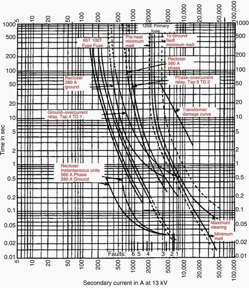
Whereas phase-to-phase faults on the 13 kV side are 0.866 of the three-phase fault value (see Figure 3), the current in one phase on the primary is the same as the three-phase fault value.
However, the primary fuse sees only 0.577 of the secondary one-per-unit current for 13 kV phase-to-ground faults (see Figure 3). The dashed-line curve to the right is the primary-fuse minimum-melt characteristic for secondary ground faults. For the 600 sec operating time, 2196 × √3 = 3804 A is equivalent to 2196 A for a phase-to-ground fault.
The transformer through-fault overcurrent limit curve is plotted as shown. As shown, the transformer is protected satisfactorily against thermal damage.
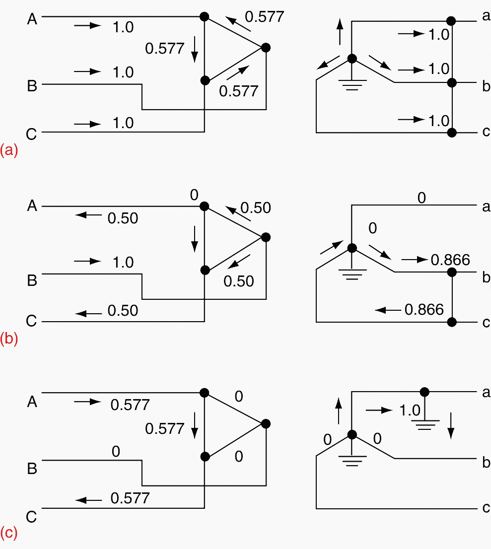
Notes on Figure 3
- Typical industry data indicate that, at 480 V, arcing phase-to-ground faults may be as low as 19% of the rated fault value.Thus, for a secondary fault maximum of 52,296 A, the primary current for the fuses would be 52,296 × 0.19 × 0.577 × 0.48 = 229 A kV, just above the 200 A rating, and it is doubtful that the fuses will give any protection until severe burning increases the fault current.
- Secondary faults on the bus should be cleared by the secondary transformer circuit breaker and faults on the feeders by their circuit breakers backed up by the transformer breaker. Thus, the primary fuses are backup for faults if they can ‘‘see’’ these secondary faults.
The 65T and 100T fuses selected on the basis of the loads served from the taps are shown plotted in Figure 2 from the manufacturer’s curves.
The left curve is minimum melt, and the right maximum clearing.
The maximum load through the recloser is 230 A. A recloser was selected with a minimum trip rating of 560 A phase, slightly more than twice the load needed to override cold load with a safety factor. The ground unit is set at 280 A by choice. The time characteristics for both units are plotted for the timed and the instantaneous operations from the manufacturer’s data.
The maximum load through the breaker and relays at the 13 kV bus is 330 A. Thus, the CT ratio of 400:5 will give a secondary current of 330/80 = 4.13 A.
Time settings for the phase and the ground relay provide a CTI of at least 0.2 sec above the recloser. This is satisfactory when the recloser time curves include fault-interruption time.
Fast, instantaneous tripping with reclosing is very useful because approximately 80%–95% of the faults on open-wire circuits are temporary. They are caused primarily by momentary tree contact because of wind, or they may be lightning induced.
Frequently, these faults can be cleared and the service restored quickly by deenergizing the line with immediate reclosing.
To provide this instantaneous tripping, phase and ground units can be applied to breakers to supplement the time units. Reclosers have either a fast or slow time–current characteristic, of which only one at a time can be used.
Several attempts can be made, usually 1–3. The particular number and sequence is based on many local factors and experiences.
In this application, the operating values do not provide a large margin over the maximum fault values for fault 1. Hence, only a short section of the line has instantaneous protection.
This is still recommended, for it provides fast clearing for the heavy close-in faults.
Fuse-saving is used to avoid fuse operations for transient faults and, thereby, avoid long outages for crews to replace them. This is accomplished by a second instantaneous unit set to overreach the fuse and, in the hope to clear transient faults before the fuse can operate.
An instantaneous reclose is attempted and, if successful, service is restored. The instantaneous unit is locked out, thereby permitting the fuse to clear a continuing fault.
Thus, for fuse-saving at the breaker, as in Figure 1, the instantaneous units could be set to operate for fault 2, but not for fault 3, or at 5374 A phase, 4763 A ground (1.2 fault 3).
However, it is important that the instantaneous unit and breaker clear faults before the fuse is damaged (minimum melt) or blown.
Figure 1 shows that the 100T fuse will be damaged at about 5000 A after about 0.03 sec (1.8 cycles at 60 Hz). Thus, the fuse will blow before the breaker opens; therefore, fuse-saving is not applicable at the breaker.
Fuse-saving is applicable at the recloser when operating on its fast or instantaneous curves. For faults on the laterals beyond faults 4, 5, or 6, the recloser will trip and reclose once or twice as programed.
If the fault is transient and cleared, service will be restored without a fuse operation. After this, the recloser operates on its slow curves, and the fault is cleared by the proper fuse on the laterals or by the recloser for faults on the feeder.
A sectionalizer could be used for fault 2 lateral circuit instead of the fuse. It would open during a dead period to clear a permanent fault on its circuit after, say, two unsuccessful fault operations by the breaker instantaneous units.
Reclosing can provide a potential liability where the circuit can be physically contacted by persons, such as downed lines at or near ground level.
Practical distribution coordination condiderations
Distribution protection practices will be found to vary considerably between utilities. This is due to the nature of the system being protected, operating experience, and the historical philosophy that has evolved within each individual utility.
Such application involves judgment in creating a balance between preventing permanent outages for faults that are temporary in nature and subjecting the entire feeder to more momentary outages than necessary.
Some utilities have abandoned fuse-saving practices because of the increasing complaints caused by the impact of momentary outages on sensitive electronic equipment. Other utilities maintain an outlook that the advantages of applying “low set” instantaneous tripping to facilitate fuse-savings outweigh the disadvantages.
Some such utilities use a low set instantaneous relay on all distribution feeders that are blocked after the first trip, and an additional high set instantaneous relay that is in service at all times.
The high set instantaneous relay provides fast clearing for high-magnitude faults, which helps prevent equipment damage and can enhance coordination, allowing for more sensitive settings to be applied on protective devices that are upstream from the line terminal breaker.
The first reclosure is typically as fast as possible with about 15 cycles allowed for arc extinction. The second automatic reclosure was set to occur in 15 sec and the third in about 145 sec.
The use of programable microprocessor-based protective devices can be applied to mitigate some of the problems encountered in protecting distribution systems.
Experience has shown that very little fault current might flow when the conductor falls on hard surfaces such as roads or sidewalks.
Ground Fault Protection & Protection Coordination
This webinar is taught by Claudio S. Mardegan of Engepower in Brazil. He will discuss the importance of calculated bolted and arcing fault, and why this value shall be as close as possible to the actual value is also discussed.
He will also talk about escalation of single-line-to-ground arcing faults, types of protection coordination, coordination time interval (CTI) determination, and where to apply CTI – general rule and particularities.
Finally, he will discuss overcurrent optimized setting, phase protection as back of ground single line-to-ground protection, and coordination of voltage relays with overcurrent relays.
Reference // Protective Relaying Principles and Applications by J. Lewis Blackburn and Thomas J. Domin (Purchase harcopy from Amazon)
Edvard Csanyi
Hi, I'm an electrical engineer, programmer and founder of EEP - Electrical Engineering Portal. I worked twelve years at Schneider Electric in the position of technical support for low- and medium-voltage projects and the design of busbar trunking systems.I'm highly specialized in the design of LV/MV switchgear and low-voltage, high-power busbar trunking (<6300A) in substations, commercial buildings and industry facilities. I'm also a professional in AutoCAD programming.
Profile: Edvard Csanyi

Very interesting and very useful too, excellent
Very nice
Excelente información y muy interesado en adquirirla gracias saludos
Thank you Trujillo!
Hello I like the article very good , but if want know more about Realys coordination for example Coordination: Relays_Fuse and Breaker….I hope your answer
This portal side help the new comer to do their best in Electrical field. So I thanks to the intire team of EEP for their work that help other Electrical Engineer in improving their technical skill.