
Estimated Study Time: 13 minutes
Modbus RS485 cabling rules
The cabling of the industrial communication systems (Modbus RS485) is different in some ways from the cabling used for power cabling and the electrician may experience some difficulties if he is not an expert in Modbus communication networks.
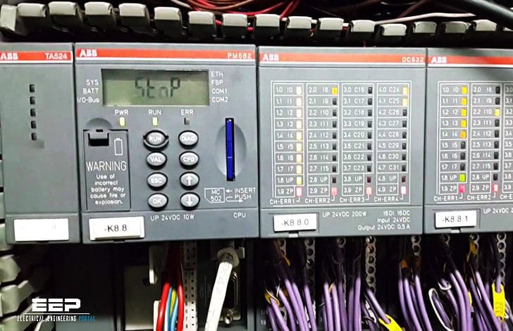 9 rules for correct cabling of the Modbus RS485 industrial communication systems (photo credit: Jose Rivas via Flickr)
A Modbus RS485 connects a Master device to one or more Slave devices. Henceforth, we shall consider Slave devices to be measuring instruments with serial communication, even if the cabling is similar for all Modbus devices.
The main rules are set out below that must be followed for the cabling of this type of network:
- About Modbus RS485
- Connection port
- Connection between the devices
- Maximum distance and maximum number of devices
- Use of repeaters
- Type of cable to use
- Connecting to the terminals
- Earth connection of the shield
- Termination resistance
- Connection to personal computer
Rules for Modbus RS485 cabling:
1. About Modbus RS485
Modbus is one of the most prevalent communication protocols in industrial automation, despite its inception in 1979. Modbus’s enduring and robust position in the landscape of industrial protocols is attributable to its simplicity and directness. It is free of charge and versatile, allowing for unrestricted implementation and adaptation to diverse applications.
The Modbus protocol necessitates minimal hardware and software resources, making it suitable for systems utilizing small and inexpensive microprocessors. The fundamental and crucial framework of the transmitted data facilitates efficient communication, achieving an optimal balance between the informative content and the total byte count transmitted.
The protocol accommodates partial command implementations tailored to specific requirements and allows for extension through the incorporation of unique commands by the device maker.
The Modbus protocol is founded on fieldbus technology, making it appropriate for the exchange of information between physically separate devices, even when they are located at significant distances from one another. The implementation of an automated machine or facility through a network of interconnected devices offers numerous advantages, including:
- Capability to implement the automation system utilizing commercially available devices from various manufacturers that are easily interchangeable.
- Strategic placement of diverse devices across the plant, even remote areas, resulting in substantial reductions and savings in I/O cabling.
- Plant fractionation leading to the simplicity of design development and maintenance or repair activities.
Watch Video – What is Modbus master-Slave
2. Connection port
Each device has a communication port with two terminals, which are indicated for the sake of convenience as A and B. In these two terminals the communication cable is connected so that all the devices that take part in the communication are connected in parallel.
All the ‘A’ terminals must be connected together and all the ‘B’ terminals must be connected together respectively.
In order to avoid errors when many devices are connected, cables of the same colour should be used for all the connections to the terminals A and cables of the same colour should be used for all the connections to the terminals B of the various devices (e.g. white for A and blue for B).
This makes it easier to identify cabling errors. The communication port on the Master device, whatever it is, has two terminals that correspond to A and B.
Watch Video – Modbus RS485 Port Settings
Go back to Modbus RS485 cabling rules ↑
3. Connection between the devices
Unlike what happens in many energy distribution systems, the manner in which the devices are connected in parallel is important. The RS485 system used for Modbus communication provides a main cable (Bus or backbone), to which all the devices have to be connected with branches (also known as stubs) that are as short as possible.
The branches must be no longer than 1200 m! Longer branches could cause signal reflections and generate disturbances and consequent errors in the reception of data.
Figure 1 shows an example of a correct Bus connection.
Figure 1[/highlight1] – Network with Bus structure

Figure 2[/highlight1] – Examples of incorrect Bus connections

Go back to Modbus RS485 cabling rules ↑
4. Maximum distance and maximum number of devices
The main cable must be no longer than 700 m! This distance does not include the branches (which must nevertheless be short). The maximum number of devices that can be connected to a main cable is 32, including the Master.
The maximum number of devices that can connect to the RS485 network is mostly determined by the specifications of the driver integrated circuits utilized in the interfaces of the individual nodes.
For instance, components with 1/2UL permit the connection of up to 64 devices, whilst those with 1/8UL can accommodate up to 256 nodes. It is important to note that this data is derived exclusively from the assessment of the unit load, omitting the polarization resistances of the bus and various other components of the specific application, particularly the quality and length of the connections, as well as the communication speed, which can significantly diminish the maximum number of devices.
Go back to Modbus RS485 cabling rules ↑
4. Use of repeaters
In order to increase the extent of the Modbus network, repeaters can be used; and signal amplifying and regenerating devices provided with two communication ports that transfer to each what they receive from the other.
Figure 3[/highlight] – If the distance segment exceeds 1200 m or the number of drivers in the segment more than 32 pieces, you should use a repeater (repeater), to create the next segment. Moreover, each segment of the network must be connected to the terminator.
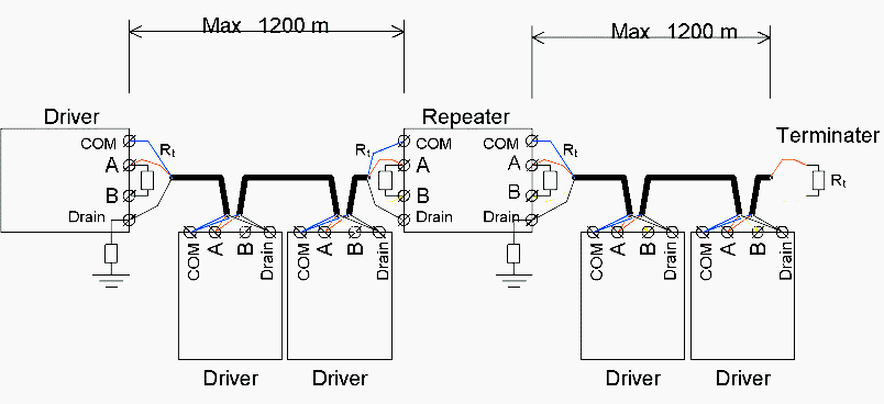
Using a repeater, the main cable is divided into different segments, each of which can be up to 700 m in length and connect 32 devices (this number includes the repeaters). The maximum number of repeaters that should be serially connected is 3. A higher number introduces excessive delays in the communication system.
Go back to Modbus RS485 cabling rules ↑
5. Type of cable to use
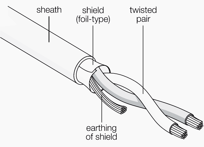
The cable to be used is a shielded twisted pair (telephone type). For example, Belden 3105A cable can be specified, but different types of cable with equivalent characteristics can be used. The twin consists of two conductors that are twisted together.
The shielding may be braided (be formed by a mesh of thin conducting wires) or be a foil (consisting of a sheet of metal wound around the conductors): the two types are equivalent.
Figure 4 – Detail of a shielded twisted pair
Go back to Modbus RS485 cabling rules ↑
6. Connecting to the terminals
In some countries, inserting two cables into the same screw terminal is permitted. In this case it is possible to connect the main inlet and outlet terminal directly to the terminals of an instrument without creating a branch.
If on the other hand each terminal can accept only a single cable, a proper branch must be created using three auxiliary terminals for each instrument to be connected.
Watch Video – Modbus RS485 Physical Connections
Go back to Modbus RS485 cabling rules ↑
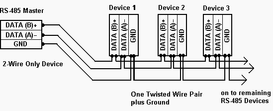
7. Earth connection of the shield
The cable shield must be earthed only in one point. Normally, this connection is made at one end of the main cable.
Figure 5 – 2-wire RS485 connection
Go back to Modbus RS485 cabling rules ↑
8. Termination resistance
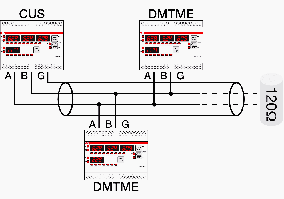
In order to avoid signal reflections, a 120 Ohm termination resistance must be fitted on each end of the main cable. The end resistance must be used only at the ends of the main cable. If the total length of the main cable is less than 50 m termination resistances can be avoided at the ends of the main cable.
Figure 6 – 120 ohm resistance connection
Go back to Modbus RS485 cabling rules ↑
9. Connection to personal computer
If the master used is a personal computer, in general an RS232/RS485 serial converter provides the connection to the bus.
Watch Video – The Modbus RS485 Unit ID
Go back to Modbus RS485 cabling rules ↑
Reference: Practical guide to electrical measurements in low voltage switchboards by ABB
Related electrical guides & articles


Edvard Csanyi
Hi, I'm an electrical engineer, programmer and founder of EEP - Electrical Engineering Portal. I worked twelve years at Schneider Electric in the position of technical support for low- and medium-voltage projects and the design of busbar trunking systems.I'm highly specialized in the design of LV/MV switchgear and low-voltage, high-power busbar trunking (<6300A) in substations, commercial buildings and industry facilities. I'm also a professional in AutoCAD programming.
Profile: Edvard Csanyi

We have connected 8 flowmeters in loop with BMS of Schneider, flowmeter sometimes communicate with BMS and sometimes not, also at the end of loop we are getting .2Volts across A and B. Whether this low voltage can cause the interruption in communication.
Pls suggest.
This is a great article, but there are a few things that have not mentioned.
1 – Never splice cables during a run. This can cause a standing wave that may eventually cause communications issues.
2 – I always recommend 1/2 watt resistors with 1% tolerance. Two resistors that are 123 ohms work better than one that is 115 and one a 123 ohms.
3 – When daisy chaining connections, never switch brands of cable or conductor sizes. Even though they may be “approved or designed for” Modbus communications, there are differences in the twist method used to create the impedance. Again, this can cause standing waves and you will have one hell of a time finding it.
Based on which standard can the above article be validated?
Thanks, Edvard, for this good information.
Thanks, Edvard, it’s very good content… however, at some points it is advised to use a single main cable and separate branches whereas in many sections and diagrams drop segments are shown using the main cable itself… it is creating confusion… please clarify…
Amazing a good deal of beneficial information!
Dear Edvard,
Other references on RS-485 wiring mention Daisy Chaining to be the best and preferred wiring solution, and Bus-and-Stub to be just workable. So could you please clarify on this, and revise your drawing and write-up accordingly?
Regards
PC
L&T
HI
We are communicating from one Semeins PLC to ABB PLC. Flow Diagram is as
Semeins PLC –> Modbus TCP output –> tg-718 Gateway –> RS485output –> TCC80–> RS232 output—>CI853 serial module of ABB.
We are able to get data in laptop through U-Port after TCC80, but data is not coming in PLC.
when I am simulating modbus slave from laptop through U-Port through same TCC80 and set of cable data is coming in controller.
I am getting 1.15 V DC on the RS485 terminal before TCC80.
what could be the reason for data not coming.
Semeins PLC and ABB PLC are in two different building which is approximately 200 meter away from each other. There is no other device in the modbus segment.
Please suggest.
Very Informative.
For a field transmitter requiring 24vDC supply is it OK to run two twisted pairs (power and Modbus) individual and overall shielded cable with a common jacket? Any recommended cable if this is good practice?
Thanks
I am also curios for this answer. You use the words field and transmitter so already you have three issues. 1. It is an industrial environment. 2. Could be considerable length of cable. 3 A transmitter would be the modbus rtu slave device so the master would have to poll often.
Short cable lengths I think modbus is very tolerable not sure about your scenario. Also you would have to factor in the voltage drop across a reasonable long distance. Comms cable is generally thinner than power cable.
Anyone else have thoughts on this subject ?
– For isolated type RS-485 communication we are using analog devices part no: ADUM2587 ic.
– Find above attached circuit for the same which we have finalized with analog devices technical team.
– We require solution for below connection problem.
Sometimes customer connects 24 VDC supply / 230 VAC supply to RS-485 communication Terminals D+, D-.
Means instrument power which connect to rs-485 communication terminal
So passive components like Varistor and TVS get burnt and also sometimes damage the Adum 2587 Ic.
– As these components are required for online protection against ESD as well as transients & over voltage protection when power is connected perfectly to supply connection
– How we can protect our ics and protection components against the wrong supply connection?
– Give us solution for the same
Good informative.
Hi
I want to share results about connect more than 32 nods to same network. I connected 42 nods in same network and it is working fine.
Hi, It is feasible but not recommended. The maximum number of devices on the network depends on electrical noise conditions, cable length and data speed.
As you increase any of them (included number of devices) you decrease reliability of your network.
If read/write function is to be established with Modbus serial link how many pair cable shall be utilized? Does it still need half duplex functionality (or) full duplex functionality is required?
Every one who writes about RS 485 only writes the rules.No one write the engineering behind it.
Why only 32 nodes?By connecting parallel how the differences in the supply voltages between nodes adjusts? While difference in voltage determines the one and zeros why common wire to be connected?
What is the calculation for length of the cable w.r.t baud rate ,cable capacitance How does the isolation helps etc., etc
Hi there, there is only 32 nodes, because that is all the protocol allowed for when they made it (i think from memory), it’s just a design thing, it could be more. DeviceNet for example supports only 64 nodes.
For the engineering behind it, you need to study communications engineering, as part of an Electrical/Electronic Degree course at University. Basically the cable limits are to do with the voltage reflections and ringing that will be produced when the voltage is pulsed down the wire, capacitance etc. will effect the rise time, and as you increase the board rate, the width of the pulses become shorter, hence there is less allowance for ringing, caused manily by poor cable installations. Hence why you can get away with bad cabling for low boad rates, but not for higher rates, as the ringing will be too much and the devices will not be able to determine the difference between the logic 1 state and the logic 0 state of the pulses.
the communication packets use 8 bit words. The entire capacity of a word is 2^8 or 256. Now modbus is using part of the word for handshaking, a 32 addressable node system is using 5 bits for address and three bits for handshaking.
Awesome stuffs!!!!
Hi Edward,
Why you so smart & you know everything!!??!! my I copy your artickle?? two thumbs for you
Regards
R.immanuel
Regarding maximum length of the cable, it depends of the communication speed. For 9600-19200 baud, the total cable length could go up to 1000m and even more (depending on the cable quality). For higher speeds cable length should be reduced. Also stubs cannot be longer than 1-2m. The value of 1200m from the article might refer to millimeter…
Another good idea for noise immunity is to use bus polarization, e.g. to insert a bias resistor network on the bus.
Hi Edvard,
I am a digital content manager at CFE Media, which publishing Control Engineering, Plant Engineering, and Consulting-Specifying Engineer.
I would like to offer you a publishing opportunity at Control Engineering. Would you be interested in writing one, or a series of articles to be published on our website and possibly print publications?
Here is the link explain the reach of Control Engineering: http://www.controleng.com/single-article/control-engineering-professional-profile/42f7d3fd47128265ab3a0204ee09d3dc.html
I can send you more documents if you’d provide your email address. :)
My email address is: [email protected]
Hope to hear from you soon.
Thanks,
Joy
In some cases , Our communication system(RS 485) is working fine. but the slave port is failure.
At the time can we check the system through Multi-meter?
how much voltage will flow through the terminal A,B?
In BMS, am facing many problems while communicating the VFD through controller. Kindly provide some troubleshooting ideas.
Regarding Vignesh Waran problem.
A very very very long time ago I hooked up my “Productivity 3000” up to what i think was a “PowerFlex 4” check out “appendix C” pg93/108 literature.rockwellautomation.com/idc/groups/literature/documents/um/22a-um001_-en-e.pdf
“RS-485 basics: When termination is necessary, and how to do it properly”
https://e2e.ti.com/blogs_/b/analogwire/posts/rs-485-basics-when-termination-is-necessary-and-how-to-do-it-properly
“…Techniques for impedance matching to minimize line reflections in several applications are presented, with laboratory test results.”
http://www.ti.com/lit/an/slla070d/slla070d.pdf
I’m old and i havn’t touched a plc or vfd in years. Forgive me.
Dear Edvard,
You are really doing great service to the electrical engineering fraternity. In order to disseminate the information, can we publish the articles in some other forums?? Pl. let me know, so that young engineers can be provided with basics as well as in depth knowledge on electrical engineering subjects.
thanks,