Switchgear Operation Logic
Dealing with the switchgear operation logic diagrams is like setting the brain functions. It needs vigilance and patience from design engineer supported with hours and hours of testing and operation simulations. This technical article brings some light to the essence of creating operation logic for for low-voltage and medium-voltage switchgear feeders.

The creation of a logic diagram marks the beginning of the preliminary design work for both low voltage (LV) and medium voltage (MV) systems. The initial stage of the design process is referred to as the base design stage, and it is comprised of the phases that are listed below.
1. Preparation of single line diagram: In this diagram, major components of substations are confirmed, such as bus bar scheme, circuit breaker, isolator, short circuit rating, continuous current rating, voltage rating, transformer ratings, etc.
2. Preparation of Relay & Metering Diagram: After completion of the single-line diagram, the next step is to prepare the relay and meter single-line line diagram (R&M SLD). At R&M SLD protection and metering devices and scheme are selected.
Operational Logic For LV and MV Switchgear Feeders:
- Keep It Simple
- Standardized the Symbol and Function Code
- Step-by-Step Guidance
- Truth Table / Operational Logic Table
- Presentation Using Logic Gates (AND, OR, NOT, NAND, and NOR Gates)
- Device Characteristics You MUST Understand
- Safety Requirements
- Short Circuit and Rated Current
- Understand the System Components for Designing the Operational Logic:
Operational Logic Design
Safe and efficient operation is the key essence while designing the operational logic for LV & MV switchgear. A switchgear operation should be a foolproof design that means any false or wrong operation is prevented or blocked by the system which is referred to by the term “Interlocking”.
Operational aspects that should be considered while designing the system are as follows.
1. Keep it Simple
An ideal operational system should be as simple as possible, simple system design not only create ease of operation but also reduces the chances of mistake. The guideline is to use clear and concise instruction. An ideal system should involve less number of operations.
Figure 1 – Components of MV switchgear feeder


Go back to the Contents Table ↑
2. Standardized the Symbol and Function Code
For a given network the right approach is to standardize the symbols and the functional codes for different devices used in the operational logic diagram.
An example of standardization is the American National Standards Institute (ANSI) organization that administrates and coordinates standards and conformity assessment systems. ANSI /IEEE Standard C37.2 Standard that deals with Electrical Power System Device Function Numbers, Acronyms, and Contact Designations.
Following is the list of some device codes used as per ANSI / IEEE Standard:
- 50 – Instantaneous Overcurrent
- 51 – AC Inverse Time Overcurrent Relay
- 52 – AC Circuit Breaker
- 83 – Automatic Selective Control or Transfer Relay
- 86 – Lockout Relay
- 87 – Differential Protective Relay
- 89 – Line Switch
A complete list of ANSI codes is available in the following document: Protection Relay – ANSI Standards
Find below the list of some suffixes:
- B -Bus
- G – Ground or generator
- L -Line
- N – Neutral
- T – Transformer
- U – Unit
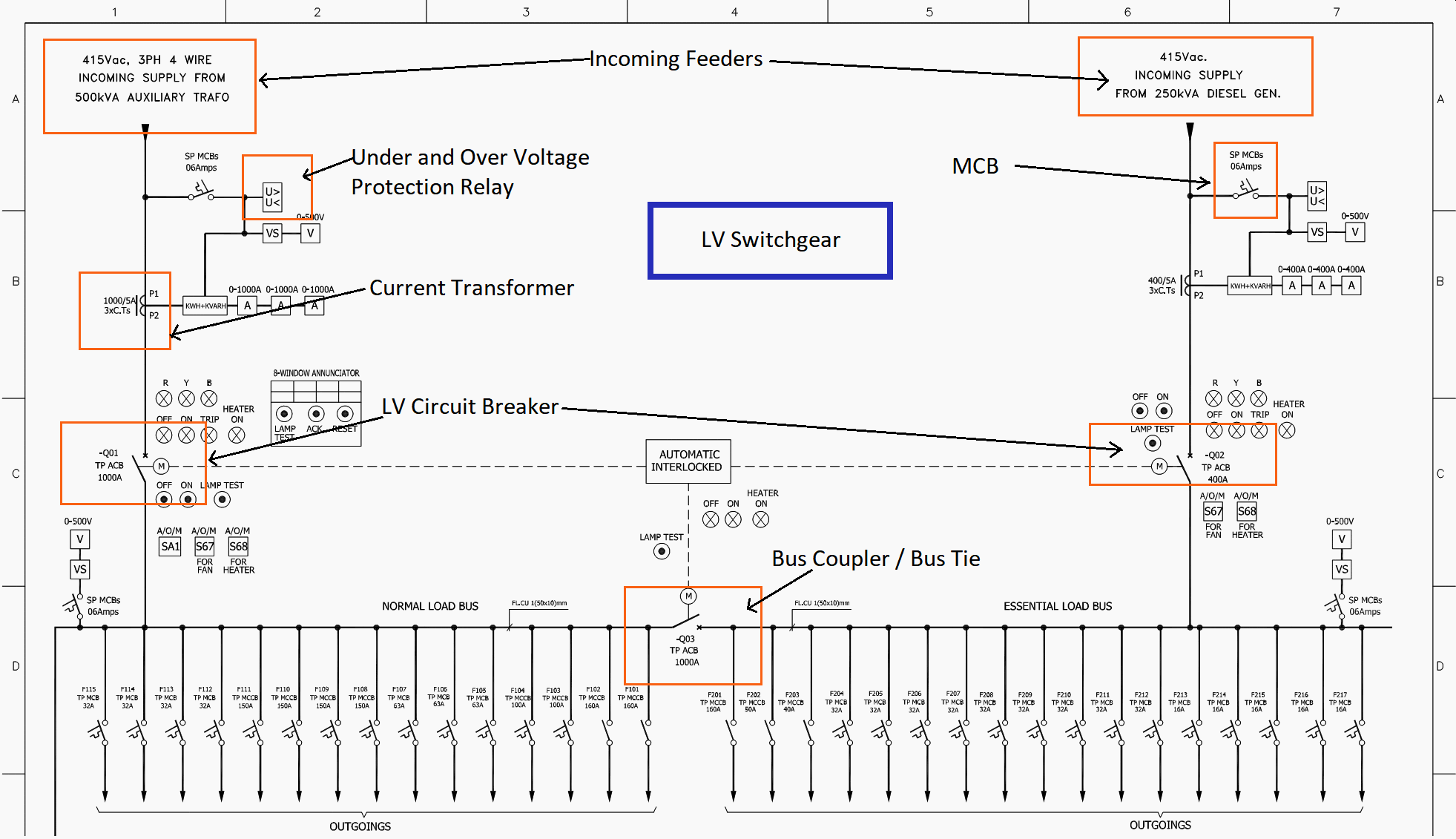
Figure 2 – LV Switchgear Single Line Diagram (click to zoom)


Go back to the Contents Table ↑
3. Step-by-Step Guidance
To reduce the risk of a mall or wrong operation detailed operation sequences are also created. These sequences define step-by-step operations, authority level, and responsibility to carry out specific tasks. Step by step guide is also referred to as Standard Operating Procedure (SOP).
An SOP is specific to the operation of a given substation or switchgear, industry regulations, and laws. SOP minimizes operational mistakes or hazards, operation of switching devices involves several risks such as.
- Closing of feeder Circuit Breaker onto earth switch closed (Temporary portable ground or permanent earth).
- Operation of Isolator on load, i.e. when the circuit breaker is closed.
- Rack in or rack out the trolley while the circuit breaker is in the close position.
- Performing the operation without permit or energization without closing all permits.
- Cancellation of the permit without removing the temporary portable earth.
- Closing bus coupler without synchronization facility.
- Allowing to give shutdown at cable compartment, while the cable is live or could be live from the other end and cable is not earthed.
- Allowing operation of circuit breaker when trip coil or coils are failed.Therefore, once the circuit breaker is closed, it can never be opened by the operator or protection device.
- Loading a transformer or generator more than its capacity.
- Energization of the feeder without confirming the remote substation earth status.
- Capacitive voltage indicators are provided in MV switchgear to check the status cable/feeder, an SOP should also define to check and confirm the status of feeder before any operation.
- MV busbar is usually provided with the voltage transformer, and the LV busbar is provided with the voltmeter hence, to check the busbar voltages should also be incorporated in operational logic.
- Wrong use of interlock bypass switch.
- Not considering the addition of fault MVA while multiple sources are connected in parallel.
Membership Upgrade Required
This content is not available in your premium membership plan. Please upgrade your plan in order to access this content. You can choose an annually based Basic, Pro, or Enterprise membership plan. Subscribe and enjoy studying specialized technical articles, online video courses, electrical engineering guides, and papers.
With EEP’s premium membership, you get additional essence that enhances your knowledge and experience in low- medium- and high-voltage engineering fields.
Black Friday Deal 💥 – Save 20% on Pro Plan with code BLACKFRIDAY
Copyright Notice
This technical article is protected by U.S. and international copyright laws. Reproduction and distribution of PDF version of this technical article to websites such as Linkedin, Scribd, Facebook and others without written permission of the sponsor is illegal and strictly prohibited.© EEP-Electrical Engineering Portal.
Related electrical guides & articles
Premium Membership
Muhammad Kashif
Muhammad Kashif Shamshad is an Electrical Engineer and has more than 17 years of experience in operation & maintenance, erection, testing project management, consultancy, supervision, and commissioning of Power Plant, GIS, and AIS high voltage substations ranging up to 500 kV HVAC & ±660kV HVDC more than ten years experience is with Siemens Saudi Arabia.Profile: Muhammad Kashif


