
Estimated Study Time: 12 minutes
Protection schemes and CTs
Various types of instrument transformers are currently in use on the basis of the varied applications of these devices. The construction aspects and sizing play an important role in the selection of proper types of both CTs and VTs.
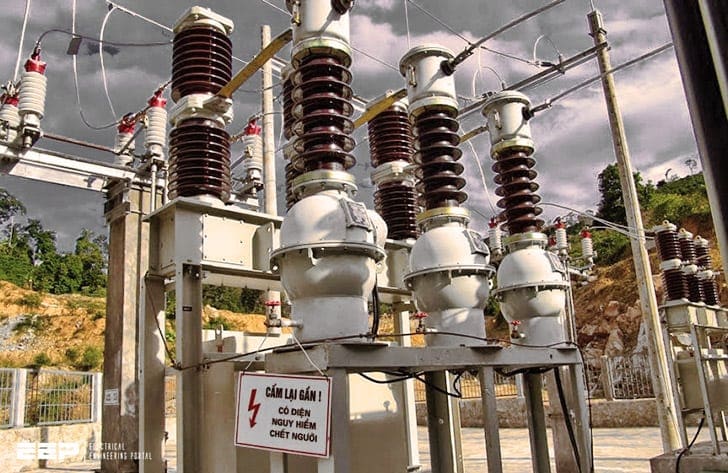 Applying CTs in protection schemes for transformers, generators, machines etc.
The design principles of these transformers are different from those of power transformers because accuracy is of prime importance and these transformers are lightly loaded in comparison to power transformers.
This technical article explains seven applications of CTs in protection schemes for machines, generators, generator-transformers, transformers, transmission lines, etc. as well as the most important design considerations:
- Application of CTs in various protection schemes:
- Important design considerations:
Application of CTs in various protection schemes
1. Differential Protection
Differential protection is used for the protection of generators, generator-transformers, transformers, transmission lines, large motors, bus zones, etc.
The protected zone is determined by the location of CTs or VTs secondary.
In Figure 1, X is the winding of the machine to be protected. During healthy condition, the current entering in X is equal in phase and magnitude to the current leaving X. CT1 and CT2 are of such a ratio that during the normal conditions or for external faults, the secondary current of a CT is equal.
The vector differential current I1 − I2 through the relay coil is therefore zero, i.e. I1 − I2 = 0 during normal conditions or for external faults.

When a fault occurs in the protected zone, the current entering the protected winding is no longer equal to the current leaving the winding as some current flows to the fault.
The differential current I1 − I2 flows through the relay operating coil and the relay operates if the operating torque is more than the re-straining torque.
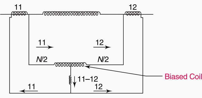
2. Percentage or Biased Differential Protection
In the above paragraph, we have discussed how differential protection of various machines is achieved. But in actual conditions, the differential relay has to overcome the trouble arising out of the differences in CT ratios for high values of external short-circuit currents.
The differential relay is provided with an additional coil, i.e. a re-straining coil.
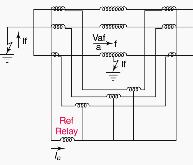
3. Restricted Earth Fault Protection
When the earth fault occurs at, say, point ‘f’ of generator winding, voltage VAF will be available which will drive fault current IF through neutral to ground connection. This voltage VAF will be relatively less when the fault point is nearer to terminal ‘a’.
Hence IF will also be reduced but if the relay setting is kept too low, it may respond during through faults.
In practice, only 85% of the generator winding is protected against a phase-to-earth fault and 15% of the portion is left unprotected.
4. Interposing CT
An intermediate CT (or shorter ICT) is used for feeding protective or measuring devices which require operating current that is different from the main CT secondary current.
5. Core Balance CT (CBCT)
A core balance CT (or CBCT) is used in sensitive earth fault protection schemes. The CBCT is a ring type LTCT put around a three-core cable to detect zero sequence current (earth leakage current in the system).
For single-core cables, all three cables must pass through a CBCT. The CBCT secondary feeds a sensitive earth fault relay.
Since the magnetising current and primary current are of the same order, the ratio of a CBCT is very significant, but one has to verify the operation of the relay at a specified current.

The termination of a three core cable into three separate lines or bus-bars is through cable terminal box. The core balance protection is used along with the cable box and should be installed before making the cable joint.
For eliminating the error due to sheath current (Ish) the earthing lead between the cable box and the earth should be taken through the core of the core balance protection.
Thereby the error due to sheath current is eliminated. The cable box should be insulated from earth.
6. Summation CT
A summation CT seen in Figure 4 is used for the vector addition of several feeder currents. It may be noted that the main CT ratio of feeder CTs 1 and 2 should be the same.

7. Current Balance CT
A special use of CTs is in a current balance scheme. It comprises a set of two numbers. The CTs used in this scheme per phase is known as a ‘current balance CT‘.
Figure 5 shows the two circuit breakers CB1 and CB2, each feeding half the total load current (I). This arrangement is necessitated when a CB manufacturer does not have a CB of full impedance of paths A-CB1-B and A-CB2-B. Since the latter cannot be identical, the currents in the two paths will be:
I1 ≠ I2 ≠ I/2
This makes the apparent impedance of both branches equal and I1 becomes approximately equal to I2.

Important design considerations
1. Selection of Secondary Current Rating
For a given distance between the burden (relay or instrument) and the CT, the adoption of 1 A as the rated secondary current reduces the lead burden to 1/ 25th of its value at 5 A secondary current.
Also, 1 A secondary current would, all other things being equal, develop five times the peak voltage that of a 5 A secondary.
2. Selection of Primary Current Rating
The ratio error and phase error of a measuring CT are influenced by the number of available primary ampere-turns to a greater extent than by any other single factor, and this is equally true for the performance of a protective CT.
Thus there is a minimum value of primary current for any particular application for which a ring type or similar CT may be used without making it unduly large or expensive.
If the rated primary current is below this value, it is suggested that wound-primary construction be used but again there is a minimum limit determined this time by the maximum dynamic and thermal stresses for a given class of accuracy and burden. The lower the rated primary current, the larger would be the core required.
3. Selection of Rated Burden
The ratio error for any particular value of the flux density is lowest for an overall secondary power factor of unity. The difference between the actual and test values of the ratio error depends upon factors such as:
- The flux density,
- The proportion of the total secondary circuit impedance supplied by the secondary winding, or
- The core material and the type of core construction.
In any application that demands high accuracy, the errors of CTs must be measured wherever possible with the working burden and not with the rated burden.
The rated burden should be kept as near to the actual burden as possible to obtain better accuracy.
4. Selection of Class of Accuracy
The class of accuracy should be chosen carefully as it directly affects the size and cost of the CT. This effect applies more to lower ratio CTs.
Reference // Handbook of switchgears by BHEL – Bharat Heavy Electricals Limited
Related electrical guides & articles


Edvard Csanyi
Hi, I'm an electrical engineer, programmer and founder of EEP - Electrical Engineering Portal. I worked twelve years at Schneider Electric in the position of technical support for low- and medium-voltage projects and the design of busbar trunking systems.I'm highly specialized in the design of LV/MV switchgear and low-voltage, high-power busbar trunking (<6300A) in substations, commercial buildings and industry facilities. I'm also a professional in AutoCAD programming.
Profile: Edvard Csanyi

very informative platform, please keep it flowing.
Your method/type 5 may not work properly if the sheath material is ferro magnetic, the balance core CT has short circuit of magnetic flux at the possition installed.
Dear Sir,
My question is that i want to achieve Differential Protection of motor and i have following condition
Breaker side CT is 500/1 Amp
Motor Side CT is 200/1 Amp
is it possible or there will be some issue than what kind of issue.
Regards
I need weekly updates
the nomenclature or the element of doing the job is not clear as the theory is given but it is now some how clear for me thank you
This article is very important for me because concerning the theoritical analysis is ok but the instrument or the nomenclature of the element sensitive can say not very clear or situated
Nice Information Mr. Edwards
As always, this article by Mr. Edward is very informative. Thank you.
Cheers …. beautiful explanations.
I have a query and can it be raised here?
Regards
Very informative Article Edvard. Cheers