
Estimated Study Time: 24 minutes
What’s the role of CTs and VTs?
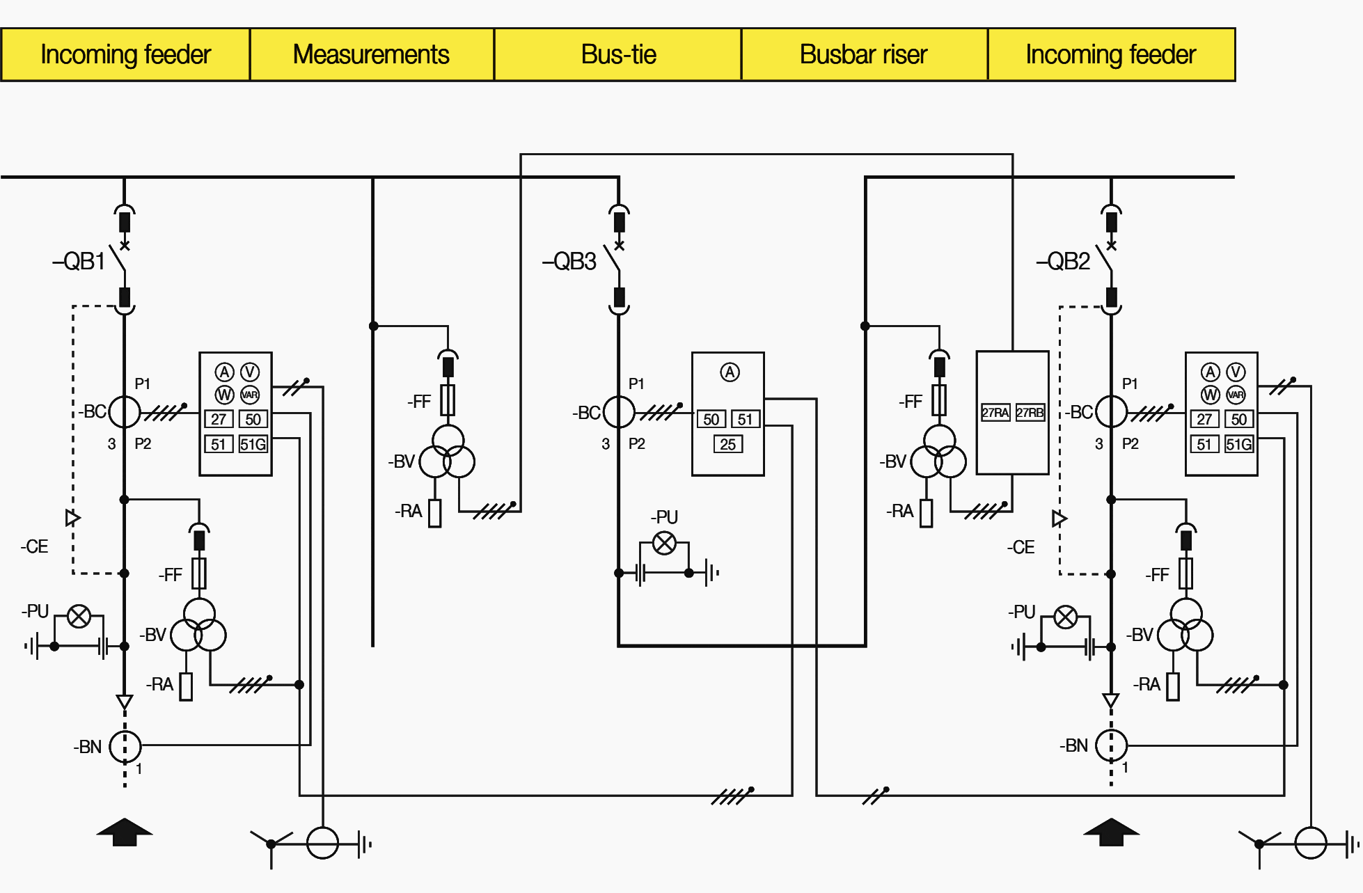
The CTs (current transformers) and VTs (voltage transformers) are provided in the plants to reduce the voltage and current values of the plant to values such as to be able to be detected by measurement and protection devices.
 Current and voltage transformers (CTs, VTs) as an integral part of protection chain
They also make the secondary measurement and protection circuits galvanically independent in relation to the primary power circuit, at the same time guaranteeing greater safety for operators (a point of the secondary winding of the instrument transformer must always be connected to ground).
For correct identification and removal of the fault it is necessary for all the components to operate correctly.
The transducers, CTs and VTs, represent an extremely important element in the protection chain and inadequate selection of their respective characteristics can lead to inadequate protection of the network and machines or to unwanted trips (which in many cases are even more damaging).
The instrumentation which is installed in the plants is generally of electronic or digital type which has reduced consumption on the secondary of the measurement transducers, CTs and VTs (in general less than or equal to 0.5 VA, unlike the old electromechanical devices which had consumptions of several VA (e.g. 5-10 VA per phase).
The presence of digital instruments has also had a significant impact on the current and voltage transformers, leading to CTs and VTs being constructed with different technologies.
In practice, since only one signal is required at the CT and VT secondary and no longer a significant power (the power needed to make the protection relay operate is taken from the auxiliary power supply), the use of air transformers (CTs) and voltage dividers (VTs) is becoming increasingly widespread.
- Inductive transformers
- Inductive current transformers (CTs)
- Inductive voltage transformers (VT)
- Non-inductive current and voltage sensors
1. Inductive transformers
The main Standard references for the inductive type of CTs and VTs (with iron laminates) in medium voltage networks are:
- EN 60044-1 current transformers;
- EN 60044-2 voltage transformers.
The construction characteristics and definition of the precision classes are given in these Standards.
Considering the present low consumptions of the device connected to the secondary, it is therefore essential for the performance of the VTs (both of measurement and of protection) as well as of the instrument CTs to be limited to guarantee that the transducer operates in the precision class for which it has been provided.
2. Inductive current transformers (CTs)
An important clarification must be made regarding the CTs relative to their construction shape and to the method of measurement. This refers particularly to ring CTs which are CTs to all effects and must be classified as such.
The CT can be of:
Wound type
Wound type (as CTs inside medium voltage switchgear normally are), with the two terminal clamps of the primary circuit and the two terminal clamps of the secondary circuit taken outside.
The primary circuit can, in this case, also have a number of turns different from 1.

Busbar bushing type
Busbar bushing type where there is a piece of busbar (normally made of copper) already embedded in resin. In this case, the terminals of the primary winding are the ends of the busbar, whereas the ends of the secondary winding are taken to external terminals.
In any case, the number of primary turns in this case is always 1.

Ring type
Ring type where the primary is not provided and it will be made up of the conductor which passes through the central hole of the CT.
The ends of the secondary winding are taken to two external terminals. In this case the number of primary turns is in any case normally 1 unless the conductor is made to pass several times in the CT.

These CTs can also be constructed as the openable type for easier installation in existing plants.
The precision classes are the same for all the types of CTs, and are defined in accordance with the Standard. According to how the CT is inserted in the network, it can carry out very different measurements.
In particular:
- CT which is inserted on just one phase (for example, a ring CT which embraces just one phase) measures line currents (of phase);
- CT which is inserted on three phases (for example, a ring CT which encloses the conductors of the three phases inside it) measures the vectorial sum of the currents (in reality the sum of the flux) and therefore the homopolar current.
What has previously been underlined is to indicate that regardless of the construction shape, the measurement which is obtained at the secondary of the CT is a function of the way in which it is inserted in the network.
The CTs serve to translate currents from the power circuit to the measurement circuit. They are classified into two types by the Standard:
- Instrument CTs measuring instruments, such as ammeters, watt meters, converters, etc. are connected to;
- Protection CTs to whose secondary the protection relays are connected.
Consequently, to obtain correct use of the digital relays, the CTs must be chosen with double precision class, for example:
100/1 – 4 VA – Cl. 0.5 + 5P10
The two precision classes are defined for different ranges of CT operation and can therefore coexist.
In the same way as described for the CTs, the same reasoning can be made for the VTs. Therefore when for example ABB’s protection relay REF 54x type relays are used, foresight lies in selecting VTs with double precision class, for example:
6000:√3 / 100:√3 – 10 VA – Cl. 0.5 + 3P
2.1 Instrument CTs
An essential factor in selecting the instrument CT characteristics is the precision class to be guaranteed for secondary loads 25% higher than the rated performance.
When instrumentation was electromechanical, it was therefore logical to purchase CTs with high performances, but nowadays with digital instrumentation it becomes compulsory to purchase CTs with truly limited performances (typically 5 or maximum 10 VA).
The instrument CTs have as their prerogative the characteristic of saturating for currents just a little above the rated primary current to guarantee protection of the instruments (typically able to support a maximum of 20 In for 0.5 seconds) in the case of a short-circuit.
In actual fact, the CT is not loaded at the secondary with its rated performance but at a lower load. The real safety factor (F’s) is therefore higher than the rated one and a check is essential to guarantee that the instruments connected to the secondary circuit are suitably protected.
The ultimate true safety factor can be calculated using the following relation:
F’S = FS × (STA + SN) / (STA + SVERO)
Where:
- F’S – true safety factor at the actual secondary load
- FS – CT rated safety factor
- SN – CT rated load
- SCT – CT self-consumption = RCT × I2N2
- I2N – CT rated secondary current
- RCT – CT secondary resistance at 75 °C
- STRUE – true load at CT secondary = I2N2 × (RINSTRUMENTS + RC)
- RC – rexistence of the wiring circuit
- RINSTRUMENTS – load (self-consumption) of the instruments connected to the CT secondary
Two examples can be of help regarding selection of the characteristics of the instrument CT and the errors which are made in the case of oversizing.
Consider a CT with a 100/1 ratio with secondary load made up of an ammeter (0.5 VA self-consumption) and a multi-function converter (0.5 VA self-consumption). 0.1 ohm resistance in the secondary circuit between the CT terminals and the instruments.
Example 1
CT 100/1 – Cl. 0.5 – 4 VA – FS = 5 – RCT = 0.8 ohm
The real secondary load is 1.1 VA, i.e. 27.5% of the rated performance, therefore the precision class is guaranteed. The real safety factor is:
F’S = FS × (STA + SN) / (STA + SVERO) = 5 × (0.8 + 4) / (0.8 + 1.1) = 12.6
The CT saturates for currents lower than the withstand one of the instruments connected to the secondary and is therefore suitably dimensioned.
Example 2
CT 100/1 – Cl. 0.5 – 10 VA – FS = 10 – RCT = 0.8 ohm
The real secondary load is 1.1 VA, i.e. 11.5 % of the rated performance, therefore the precision class is not guaranteed. The real safety factor is:
F’S = FS × (STA + SN) / (STA + SVERO) = 10 × (0.8 + 10) / (0.8 + 1.1) = 57
It is therefore obvious how every secondary of the instrument CT must be precisely dimensioned so as to avoid serious damage to the plant in the case of a fault and to be able to obtain measurements in the required precision class.
2.2 Protection CTs
The CTs which are associated with the protections have the peculiarity of not saturating until protection tripping is guaranteed for the overcurrent short-circuit.
The parameter which defines the value within which the response is linear in protection CTs is the ultimate precision factor (FL), normally equal to 10-15-20 or even higher.
In selection of the protection CT characteristics (performance and ultimate precision factor) the following conditions must be respected:
- The performance of the CT must be higher than the secondary load (relays and cabling);
- The CTs to be associated with the overcurrent protections must not saturate until safe operation is guaranteed. For example, for the ABB relays it can be considered that saturation must take place at least at double the setting value with a minimum of 20 In, but precise values can be found in the catalogues of the various types of relays;
- The CTs to be associated with particular protections, such as differential, distance relays, etc. must have safety factors defined case by case and indicated in the relay catalogues of the relays;
- The CTs must saturate for very high currents to preserve the relay and the secondary circuits in the case of a short circuit.Typically overcurrent relays have a tolerability of 100 In for 1 second and 250 In peak, but more precise values can be found in the catalogues of the various relays.
The latter condition is generally not highly considered and can be the cause of serious damage to the components if it is not verified.
As for the ultimate safety factor for the instrument CT, the true ultimate precision factor for the protection CT must also be calculated according to the load actually connected to the secondary, and can be calculated using the following relation:
F’L = FL × (STA + SN) / (STA + SVERO)
Where:
- F’L – true accuracy limit factor at the real secondary load
- FL – rated accuracy limit factor of the CT
- SN – rated load of the CT
- SCT – CT self-consumption = RCT × I2N2
- I2N – rated current of the CT secondary
- RTA – resistance of the CT secondary at 75 °C
- SREAL – true load at the CT secondary = I2N2 × (RRELAY’ + RC)
- RC – resistance of the wiring circuit
- RRELAY’ – load (self-consumption) of the relays connected to the CT
As for the instrument CT, two examples can be significant for verifying the characteristics of protection CTs.
Consider a CT with a 100/1 ratio with secondary load made up of an overcurrent relay (self-consumption 0.05 VA). Resistance of the secondary circuit between the CT terminals and 0.1 ohm relay, therefore the real secondary load is equal to 0.15 VA.
Example 1
CT 100/1 – 4 VA – 5P10 – RCT = 0.8 ohm
The ultimate real precision factor is:
F’L = FL × (STA + SN) / (STA + SVERO) = 10 × (0.8 + 4) / (0.8 + 0.15) = 50.5
The CT saturates for suffciently high current for an overcurrent protection (maximum relay setting, in general not higher than 20 In). The relay and the whole secondary circuit (terminals and wiring) are adequately protected against very high short-circuit.
Example 2
CT 100/1 – 10 VA – 5P20 – RCT = 0.8 ohm
The ultimate real precision factor is:
F’L = FL × (STA + SN) / (STA + SVERO) = 20 × (0.8 + 10) / (0.8 + 0.15) = 227
If the CT is inserted in a circuit in which the short-circuit current is high (for example a 31.5 kA switchgear), in the case of a short circuit instead of tripping of the protection due to the opening command of the circuit-breaker, there is probably destruction of the relay with the consequences which can be imagined.
It is therefore obvious how every secondary must be precisely calculated for the protection CTs as well, so as to avoid serious damage to the plant in the case of a fault and to be able to guarantee the safe protection of the subtended part of the network.
3. Inductive voltage transformers (VT)
For voltage transformers, both for measurement instruments and for protection relays, the same rule as the one for the instrument CT is valid regarding the range within which the precision class is guaranteed: the precision class is only guaranteed if the secondary load is 25% higher than the rated performance.
It is not easy to manage to ensure that a VT operates in the precision class when an instrument is connected to the secondary (relay or measurement instrument) which has a self-consumption of fractions of VA.
The use of ballast loads (resistances) to be inserted on the secondary of the VT when these have been chosen with performances which are too high to be able to guarantee the precision class, presents two problems:
- An element is added to the circuit (which can also be for protection) which can break down and therefore reduce the overall reliability of the system.
- A heating element is introduced in the instrument compartments of the switchgear with obvious problems for extracting the heat.
When selecting the VT, any ferroresonance must be taken into account. The ferroresonance phenomenon is a typical aspect of VTs inserted in cable networks with isolated neutral or not efficiently grounded.
Owing to the frequency of this oscillation, a permanent and high circulation of current is produced just in the primary winding.
Since this current is only magnetising, the secondary winding is little involved, so there is a lot of heating at the primary and negligible heating on the secondary.
Abnormal heating of the windings always produces a strong internal pressure, consequently breaking the external housing.
The measures taken to prevent ferroresonance phenomena are mainly to:
- Increase the magnetisation impedance of the VT;
- Use VTs which work with lower induction than the predicted one;
- Use VTs with high permeability iron;
- Insert damping resistances (or, in any case, devices with non-linear resistance) in series with the secondary windings connected with open delta (the voltage relay must be connected in parallel with the anti-ferroresonance resistance).
In the past, a secondary set of three VTs connected with open delta was used to measure the homopolar voltages (needed to identify the ground faults).
4. Non-inductive current and voltage sensors
Since the power absorbed by the devices connected to the secondary circuit is extremely limited, it is no longer necessary to have magnetic circuits for the coupling between the primary and secondary circuit.
Current sensors or air CTs (Rogowsky coils) and voltage sensors (voltage dividers) have therefore been developed, which eliminate the negative aspects of the inductive type of transformers (hysteresis cycle).
Particular reference is made to:
- Saturation: the saturation phenomenon does not exist with current sensors (there is no iron) and therefore definition of the ultimate precision factor is no longer a problem;
- Performance: the previous examples showed how difficult it is to reconcile the performance of the instrument transformers with the loads connected to the secondary. In fact, the need to have at least 25% of load to guarantee precision is no longer a problem;
- Rated primary currents and voltages: the linearity of response allows 95% of the applications to be covered with just two or three types of transducers, with considerable advantages for standardisation of the switchgear compartments and the possibility of their rapid re-conversion;
- There is no longer the need to have instrument CTs or VTs and/or Protection CTs or VTs since precision is constant and there is no longer the problem of saturation.
For current sensors or air CTs, the main characteristic is that these are transformers whose magnetic circuit is replaced by air.
As already pointed out, there are no saturation phenomena, but as a negative aspect there generally the precision class, which in present-day design does not reach the characteristics which can be had for the inductive type of instrument CTs.
The main characteristic for the voltage sensors is the lack of ferroresonance phenomenon (obviously because there is no longer any iron).
This is not a negligible advantage where there is still the use of networks run with isolated neutral. As for air CTs, in the current state of technology, the precision class of voltage dividers (VTs) does not yet reach that of the inductive type of VTs either.
Reference // Technical guide Protection criteria for medium voltage networks by ABB
Related electrical guides & articles


Edvard Csanyi
Hi, I'm an electrical engineer, programmer and founder of EEP - Electrical Engineering Portal. I worked twelve years at Schneider Electric in the position of technical support for low- and medium-voltage projects and the design of busbar trunking systems.I'm highly specialized in the design of LV/MV switchgear and low-voltage, high-power busbar trunking (<6300A) in substations, commercial buildings and industry facilities. I'm also a professional in AutoCAD programming.
Profile: Edvard Csanyi

M1829B HIGH METERING CURRENT TRANSFORMER.
See the specifications for further information.
SPECIFICATIONS;
M1829B High Metering Current Transformer is suitable for current measurement and protection of distribution equipments in 35kv AC. power supply system. It is not only widely used in compact fully insulated ring net switch cabinets and load switch cabinet but also cable distribution boxes because of its small size, light weight, open feasibility and convenient. It is very convenient that the transformer can be directly installed at connected output and input cables
Class of Accuracy 0.5
Power Frequency Withstand Voltage 3KV
Highest System Voltage == ==433 V
Nominal System Voltage ==== 400 V
Frequency ==== 50 Hz
Rated Burden====5.00 VA
Supply System===3ph Solidly Grounded Neutral System
Ratio===1000/5
Cable VA === (2L x R x I^2).
Certified and manufactured to NGV 2-2007 and DOT FMVSS 304 standards
Amazing mind , I have been enlightened . Thanks
Thanks. Very clear explanation.
Thank you Malik.
Really good information. thanks mate
Please explain the following further. I need some info on the same topic.
A peculiar fact about these types of CTs is that the secondary signal is not proportional to the primary size, but to its derivative (which, when suitably integrated in the devices connected to the secondary, allows current measurement to be obtained).
thanks for technical topics, especially protective relays.
Hello,
Thanks for the information.
But I would like you to provide some tutorial notes on CT and VT selection for different applications.
Thanks a lot…really useful.
Nice
Nice
Please give information about power electronics
Very informative article. I need soft presentation to my email address. How can it be downloaded.
Regards
Gracias colega
thanks man.
Very useful and comprehensive article.
Thanks!
Good job & presentation and information.
Thanks.