
Estimated Study Time: 9 minutes
Sensors as alternative
As an alternative for traditional primary current and voltage measurement techniques, the use of sensor technique is gaining field. This technique is typically applied to current and voltage measurement in medium-voltage metal-enclosed indoor switchgear.
There are many undeniable advantages with sensors when compared to the traditional solutions:
- Non-saturable
- High degree of accuracy
- Personnel safety
- Extensive dynamic range
- Small physical size and weight
- Possibility to combine current and voltage measurement into one physical device with compact dimensions
- Environmental friendliness (less raw material needed)
The above statements are discussed in more detail in the following paragraphs while introducing the sensor techniques and the actual related apparatus. Let’s say a word about each type of sensor and some conclusion at the end:
- Current sensors
- Voltage sensors
- Combined sensors
- Conclusion and answer on why sensors are not 100% alternative
Current Sensors
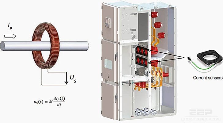
The measurement of current is based on the Rogowski coil principle. The Rogowski coil is a toroidal coil without an iron core. The coil is placed around the current-carrying primary conductor. The output from the coil is a voltage signal, proportional to the derivative of the primary current.
The signal is then integrated in the secondary device to produce a signal proportional to the primary current wave form.
The open-circuited traditional current transformer produces dangerous voltages to the secondary side and lead to a serious overloading of the transformer. Since the output from the current sensor is a voltage signal, the open-circuited secondary conditions do not lead to a dangerous situation, neither to human beings nor apparatus.

The transmitted signal is a voltage:
Uout = M · dip / dt
For a sinusoidal current under steady state conditions the voltage is:
Uout = M · j · ω · Ip
With traditional current transformers, the ratio of the CT is fixed to one value, or in case of multi-ratio CTs, to several values. These values are chosen according to the specific application needs and load currents.
With a current sensor, the situation is simpler, since one type of sensor covers a range of primary currents and in optimum case the whole installation can be covered with one type only.
To give an idea of the secondary-voltage signal level, one fixed point (ratio) inside the rated current range could be 400 A primary value, typically corresponding to 150 mV secondary signal level.

The problems related to saturating iron core in conventional current transformers can be overcome with the sensor technology. The below figure demonstrates the difference between the secondary-signal performance for both traditional current transformer and current sensor.
 and primary current (IP)")
Due to the compact size of a current sensor (no iron core), there are better possibilities to integrate the measurement devices inside other constructional parts of a metal-enclosed switchgear.

Voltage Sensors
The measurement of voltage is based on voltage divider. Two main types are available, namely the capacitive one and the resistive one. The output in both cases is a low-level voltage signal. The output is linear throughout the whole rated measurement range.
The considerations and protection methods against the ferroresonance phenomena, discussed with traditional voltage transformers, are not applicable with voltage sensors.

As with current sensors, also with voltage sensors it is possible to cover certain voltage range with one sensor type. To give an idea of the secondary voltage signal level, one fixed point (ratio) inside the rated voltage range could be 20000/√3V primary value, typically corresponding to 2/√3V secondary-signal level.

Combined Sensors
The sensor solution being quite compact and space saving, it is possible to combine both current and voltage sensors in one physical device. This device can be part of the switchgear’s mechanical basic construction, having other functions beside the measurement, like being a part of medium-voltage cable termination or busbar support construction.
These features give new possibilities to design switchgear constructions that are built according to specific customer needs and on the other hand they help the standardization work for the bulk type of switchgear.

Conclusion and comparison
The features of the sensor measurement technique compared to the traditional approach are shortly summarized in the figure below.
It could also be asked why the sensor approach has not totally taken over the traditional approach, at least when it comes to medium-voltage indoor switchgear. This is a very valid question and several answers could be given, depending on the viewpoint of the person answering.
| Feature | CT/VT | Sensors |
| Signal | 1/5 A / 100/110 V | 150 mV / 2V |
| Secondary cables | To be added | Included and tested |
| Linearity | No | Yes |
| Saturation | Yes | No |
| Ferro-resonance | Yes (VT) | No |
| Temperature coefficient | No | Incl. in accuracy |
| EMC | No | Shielded |
| Short-circuited secondary | Destructive (VT) | Safe |
| Open secondary | Destructive (CT) | Safe |
| Weight | 40-60 kg (CT+VT) | 2-25 kg (combined) |
| Standardisation possible | Limited | Wider possibilities |
Without going into this discussion any deeper, one valid argument is the limited selection of sensor-connectable secondary devices other than protection relays (IEDs).
Reference // Distribution Automation Handbook (prototype) – ABB
Related electrical guides & articles


Edvard Csanyi
Hi, I'm an electrical engineer, programmer and founder of EEP - Electrical Engineering Portal. I worked twelve years at Schneider Electric in the position of technical support for low- and medium-voltage projects and the design of busbar trunking systems.I'm highly specialized in the design of LV/MV switchgear and low-voltage, high-power busbar trunking (<6300A) in substations, commercial buildings and industry facilities. I'm also a professional in AutoCAD programming.
Profile: Edvard Csanyi

The voltage divider formula for capacitor that has been mentioned above contains mistake. It should be Uout= C1/ ( C1+C2) * Up
Some useful links:
http://cired.net/publications/cired2017/pdfs/CIRED2017_0709_final.pdf
https://www.pes-psrc.org/kb/published/reports/Practical%20Aspects%20of%20Rogowski%20Coil%20Applications%20to%20Relaying_Final.pdf
Great Article Edvard. Share more useful.
Nice and informative article
There is actually an amplifier interface from a German company Kries which converts the low power of sensors to the typical 100/150V needed for conventional IEDs.
Nice presentation.
Hi Edvard,
Good article, but your last point nails the problem – there are hardly any IEDs/relays that are compatible with these sensors. Do you know of any third-party amplifiers which would transform the 2-3V output of the resistive divider voltage sensors into typical 110V VT output levels so that we could use sensors in an off-the-shelf relay designed for VTs?
Regards,
Tom
Hi Tom,
there is pretty huge portfolio of products which are capable of utilizing the sensor signals. Check the Relion product family from ABB, especially from 615 series REF/REM/RED and from 620 series REF/REM. So there is not really a need for an amplifiers in between the sensor and protection relay. here is the link http://new.abb.com/substation-automation/products/protection-control/relion-product-family
ABB protection relays will work perfectly with these sensors.
perfect
interesting article although thinking why this is not possible! But design and practical was not feasible in the available resources!
Hi,
article is great, if you want to read more about Sensors and their application in Medium Voltage switchgear, ABB has its UniGear Digital solution. For more details go here : http://new.abb.com/medium-voltage/switchgear/air-insulated/iec-and-other-standards/unigear-digital
great
Happy about that these are so efficient than ct vt..but does not it have any drawbacks?? Eager to know…..
Informative
Great