
Estimated Study Time: 13 minutes
Heat losses in switchgear
It is widely accepted by all manufacturers that accumulation of heat (leading to overheating of devices) in switchgear is one of the greatest risks that could shorten the life expectancy of a switchgear, thus potentially damaging electrical and electronic devices or even lead to catastrophic failure.
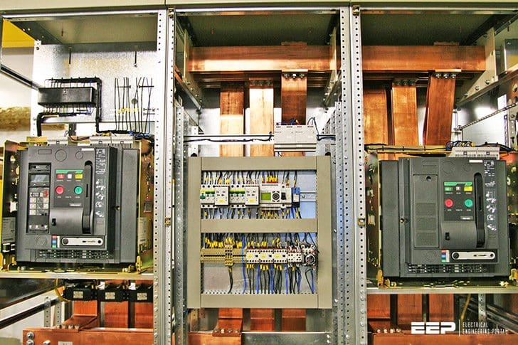 Current heat losses produced by electrical operational equipment in LV switchgear
Electrical operational equipment in switchgear and distribution systems give off current heat losses to the surroundings. In order to ensure the proper functioning of the built-in equipment, it is necessary to determine the upper temperature limits.
For any temperature rise calculation, the heat generated within the switchgear must be known.
Let’s follow the topics one by one from contents:
1. Upper temperature limit
The calculation procedure for the evaluation of the upper temperature limit is very difficult and complicated. Proof of compliance can be shown with the use of special software and tables. Computer-based evaluation (without ventilation) is used to determine the characteristics of the air over-temperature in the housing/enclosure.
This is comprised of the ambient temperature of the switchgear combination (outside the housing) and the air over-temperature inside the housing.
This determination concerns both the built-in switchgear and also the electrical connections, such as rails and isolated lines.
As long as no other conditions are specified, the ambient temperature (average over 24 hours) is taken as 35 °C and the inner temperature of the cabinet 55 °C.
In addition, the following conditions must also be fulfilled:
- The power losses must be approximately uniformly distributed within the housing.
- The air circulation must not be impeded.
- In a partially type-tested switchgear combination or in a field subdivided by partitions, there must be no more than three horizontal partitions.
- For air ducts, the cross-section of the exhaust air ducts must be at least 10 % greater than the cross-section of the air intake ducts.
- The built-in operational equipment is designed for DC and AC voltages up to 60 Hz and for a maximum power supply feeder current intensity of 3150 A.
The following points must be known in order to calculate the over-temperature:
- Smart I/O card protection type and protection class
- Type of installation of housing/enclosure
- Dimensions of housing/enclosure Type of construction (wall-mounted or floor-mounted distribution board)
- Equipment installed, heat losses, determination of space
- Location of installation (height, width and depth)
- Structure of lines
- Number of inner partitions
- Type selection
- Parts list, drawings
- Reserve space.
1.1. Differentiation of Power Losses
The power losses of the different operational equipment are taken from the manufacturers’ information and added. If the equipment is operated with a load current which deviates from the rated current, the power losses can then be described as in the following four groups:
- Power losses proportional to the square of the current, e.g. main circuits of equipment, busbars and lines:

- Power losses which are nearly proportional to the current, e.g. rectifiers and thyristors:
- Power losses which show a non-uniform behavior:
- Power losses which remain constant, e.g. magnetic coils for contactors and light bulbs:
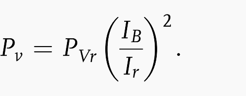

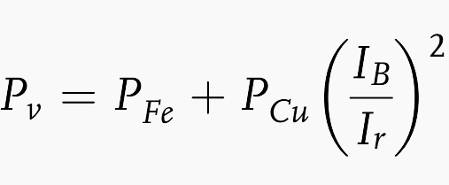
Here, the meanings of the symbols are:
- PV – Power loss
- PVr – Power loss of equipment
- IB – Load current
- Ir – Rated current
- PFe – Iron losses
- PCu – Copper losses
The planning of low-voltage switchgear, distribution and control systems must meet certain criteria. The purpose of the system must first be known, e.g.:
- Transformer stations up to 24 kV and 1250 kVA
- Low-voltage main distribution boards
- Main distribution boards
- Sub-distributions
- Motor distribution systems
- Lighting circuit distribution systems
- Power distribution systems
- Busbar distribution systems
- Distribution cabinets for reactive power compensation
- Weak current distribution systems.
2. Distribution switchgear example
The following example shown in Figure 1 illustrates the procedure for proving compliance with the upper temperature limits.
A system with the block wiring diagram shown in Figure 1 is located in a distribution switchgear with the dimensions H x W x T (2200 x 1000 x 600). The housing is a stand-alone construction and IP 5X on all sides, with no air ducts and without horizontal partitions inside.
The objective is to prove compliance with the upper temperature limits by determination of:
- Power loss from built-in equipment
- Effective cooling surface Ae
- Air over-temperature in the housing at half the height
- Air over-temperature in the housing on the top surface
2.1 Determination of power loss from built-in equipment
- 1 busbar system Cu 20 × 5 with PVr = 63 W
- 1 power circuit breaker with In = 100 A, IB = 70 A
- 1 NH1 fuse switch disconnector with In = 100 A, IB = 80 A, PVr = 15.60 W.
Pv = 15.60 W (70 A / 100A) = 7.644 W - 1 NH1 fuse switch disconnector with In = 160 A, IB = 144 A, PVr = 20 W.
Pv = 20 W (144 A / 160 A)2 = 16.2 W - 1 D01 with In= 16 A, IB = 1.55 A, PVr = 2.61 W
Pv = 2.61 W (1.55 A / 16 A)2 = 0.024 W - 1 D01 with In = 10 A, IB = 1.5 A, Pv, = 2.61 W. PVr = 2.61 W
Pv = 2.61 W (1.5 A / 10 A) = 0.058 W - 1 RCD with In = 40 A, IB = 35 A, PVr= 13.81 W
PV = 13.81 W (35 A / 40 A)2 = 10.57 W - 1 circuit breaker B16 A with In = 16 A, IB = 8 A, PVr = 4.73 W
PV = 4.73 W (8 A / 16 A)2 = 1.18 W × 4 = 4.73 W - 1 contactor with PVr = 15.7 W
- 3 relays with PVr = 3.10 W
- 3 star-delta switches with PVr = 28.6 W
- 1 external conductor with 2 x 4 x 10 mm2, at 35 °C, PVr = 4.82 W
- 1 external conductor with 2 x 3 x 70/35 mm2, at 35 °C, PVr = 8.40 W
- 1 external conductor with 4 x 2.5 mm2, at 35 °C, PVr = 3.50 W
- 1 external conductor with 3 x 1.5 mm2, at 35 °C, PVr = 2.09 W
- 1 external conductor with 3 x 2.5 mm2, at 35 °C, PVr = 3.50 W
- 1 external conductor with 4 x 25 mm2, at 35 °C, PVr = 6.25 W
The total of all power losses for the built-in equipment and lines is then 108.936 W.
2.2 Determination of the effective cooling surface Ae
Table 1 – Determination of the effective cooling surface
| A0 [m×m] | A0 [m2] | Surface factor b | Ae [column 3×4] | |
| 1 | 2 | 3 | 4 | 5 |
| Top surface | 1 x 6 | 0.6 | 1.4 | 0.840 |
| Front side | 1 x 2.2 | 2.2 | 0.9 | 1.980 |
| Back side | 1 x 2.2 | 2.2 | 0.9 | 1.980 |
| Left side surface | 0.6 x 2.2 | 1.320 | 0.5 | 0.660 |
| Right side surface | 0.6 x 2.2 | 1.320 | 0.5 | 0.660 |
| Ae ∑ (a0 b) = total 6.12 | ||||
The individual surfaces are calculated from the dimensions of the housing. The appropriate surface factors b can be taken from Table 1 above.
2.3 Air over-temperature in the housing half height
The determination of the air over-temperature in the housing at half the height Δ t0.5 follows from the relationship:
Δ t0.5 = k d Pxv
Where:
- Factor k – It follows from Figure 2 for housings closed on all sides with Ae > 1.25 m2 that Ae = 6.12 m2 and k = 0.140.
- Factor d – It follows from Table 3 for housings closed on all sides with Ae > 1.25 m2 and 0 horizontal partitions that d = 1.0.
Table 2 – Factor d for an effective cooling surface Ae 1.25 m2
| Number of horizontal partitions | Blower without air duct | Blower with air duct |
| 0 | 1.00 | 1.00 |
| 1 | 1.05 | 1.05 |
| 2 | 1.15 | 1.10 |
| 3 | 1.30 | 1.15 |
Table 3 – Exponent x for housing closed on all sides with an effective cooling surface Ae
| Housing | x | |
| Ae > 1.25 m2 | Ae < 1.25 m2 | |
| Without air ducts | 0.804 | 0.804 |
| With air ducts | 0.715 | |
- Exponent x – It follows from Table 3 for housings closed on all sides with Ae > 1.25 m2 that x = 0.804.
Substituting these values in the relationship above: Δ t0.5 = k d Pxv = 0.140 × 1.0 × 219.9120.804 = 10.69 K

4. Air over-temperature in the housing top
The determination of the air over-temperature in the housing on the top surface Δ t1.0 follows from the relationship:
Δ t1.0 = c Δ t0.5
The factor c is taken from Figure 4 for housings closed on all sides with Ae > 1.25 m2. This requires a knowledge of the variable:
- f = (H in m)1.35 / AG in m2
- f = 2.21.35 / 1.0 ×0.6
- f = 4.832
With this, from curve 3 (stand-alone medium housing) c = 1.37. Substituting this value in the relationship above, we obtain:
Δ t1.0= c Δ t0.5= 1.37 × 10.69 K = 14.65 K

For the calculated temperature of 14.65 K, at an ambient temperature of 35 °C a cabinet temperature of 49.65 °C will set in. Since (according to information of the manufacturer) a temperature of 55 °C is permissible, this constitutes proof that the upper temperature limits are satisfied.
Here the symbols have the meanings:
- Ae – Effective cooling surface of the housing
- A0 – Individual areas of the outer housing parts
- H – Height of housing
- AG – Floor area of housing
- b – Area factor
- c – Temperature distribution factor
- d – Factor for temperature rise with horizontal partitions inside housing
- k – Housing constant
- n – Number of horizontal partitions inside housing (maximum 3)
- P – Effective power loss of operational equipment built into housing
- x – Exponent
- Δ t – Overall air overtemperature in housing
- Δ t0.5 – Air overtemperature at half height within housing
- Δ t0.75 – Air overtemperature at 3/4 height within housing
- Δ t1.0 – Air overtemperature within housing at upper edge of housing.
References //
- Analysis and design of low voltage power systems by Ismail Kasikci (Get hardcopy from Amazon)
- Condition Monitoring in Low Voltage Circuit Breaker Technology by Tom Craig B.Eng (Hons) MIET Terasaki Electric (Europe) Ltd., UK
Related electrical guides & articles


Edvard Csanyi
Hi, I'm an electrical engineer, programmer and founder of EEP - Electrical Engineering Portal. I worked twelve years at Schneider Electric in the position of technical support for low- and medium-voltage projects and the design of busbar trunking systems.I'm highly specialized in the design of LV/MV switchgear and low-voltage, high-power busbar trunking (<6300A) in substations, commercial buildings and industry facilities. I'm also a professional in AutoCAD programming.
Profile: Edvard Csanyi

This article is very informative. Articles on The EEP have been so helpful and educative to me.
One things which i like to follow EEP. There are a lot of Engineering tools in it. Highly appreciated
pitty you dont allow in PDF to down load.
Very good article. But I have noted that in few places the term partially type tested is used. In the new IEC 61439 , partially type tested is not used or rather not allowed. Appreciate if you could clarify.
Thanks and Regards
PK Srinivasan iyer
HiMr.Edvard Csanyi,
I am Very happy to tell you that, your EEP is very much helpful to me. I am working in UAE as a quality control engineer, I managed to download & follow the Schneider low voltage building technology (How to Assemble low voltage switchgear).
Could you please provide a similar booklet for Siemens Sivacon 8PQ and 8PT switchgear, as we are manufacturing Siemens LV Boards. Additionally please provide me FDB, SMDB, DB etc Assembling manuals if possible, its only for my cross verification/reference to what we are manufacturing.
Very informative. Am enjoying it.