
Estimated Study Time: 10 minutes
Residual current devices (RCDs)
All residual current devices are made up of at least two components. First component act as the eyes of RCD – sensors – must be able to supply an electrical signal which is useful when the sum of the currents flowing in the live conductors is different from zero.
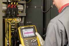
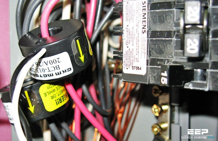 Current sensors as the eyes of RCD and tips for their correct installation (photo credit: NLCPR.com)
Second component, the brain is measurement relay – compares the electrical signal supplied by the sensor with a set-point value and sends, with a possible deliberate delay, the opening order to the associated breaking device.
Let’s talk now about an eyes of residual current device (RCD) – Sensors.
- The toroidal transformer
- The current transformers (CT)
- Special cases:
- Using an RCD with built-in toroid
Types of current sensors in RCD operation
Two types of sensors are normally used on AC circuits:
- The toroidal transformer, which is the most common for measuring leakage currents.
- The current transformers, used in HV and MV and sometimes in LV.
The toroidal transformer
This covers all the live conductors and is thus excited by the residual magnetic field corresponding to the vector sum of the currents flowing through the phases and the neutral. Induction in the toroid and the electrical signal available at the terminals of the secondary winding are thus the image of the residual current.
This type of sensor is used to detect residual currents from a few milliamperes to several dozen amperes.

The current transformers (CT)
To measure the residual current of a 3-phase electrical circuit without neutral, three current transformers must be installed as shown in figure 2.
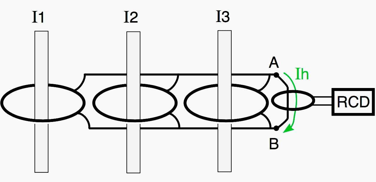
The three CTs are parallel-connected current generators, causing circulation between A and B of a current which is the vector sum of the three currents and thus the residual current.
During use, care must be taken with the CT accuracy class: with CTs of 5 % class, it is prudent not to set earth protection below 10 % of their nominal current. The HV electrical installation standard NF C 13-200 specifies 10%.

Special cases
1. High power supply
The Nicholson CT circuit, which would be useful in LV when the conductors are large cross- section bars or cables for the transmission of strong currents, does not allow, even with coupled CTs, settings that are compatible with protection of people (threshold I∆n ≤ UL / Ru).
There are a number of solutions:
Solution #1
If the problem occurs in a main switchboard downstream of the transformer, the following may be considered:
Either installation of a toroid at the supply end of the installation on the earthing connection of the transformer LV neutral (see fig. 4). This is because, according to the Kirchhoff node law, the residual current detected by (N) is strictly the same as that detected by (G) for a fault occurring in LV distribution,
Or installation of a toroid on each outgoer, all parallel-connected to a single relay (see fig. 5). When the measurement relay (normally electronic) only needs a very weak electrical signal to operate, the toroids can be made to operate as “current generators”.
When parallel-connected, they give the image of the vector sums of the primary currents.

Although this circuit is laid down in the installation standards, the approval of the RCD manufacturer is preferable. However, for discrimination reasons, it is preferable to use one RCD per outgoer.
Solution #2
If the problem arises with parallel-connected cables which cannot all cross a toroid, a toroid can be placed on each cable (including all the live conductors), and all the toroids can be parallel-connected (see fig. 5).
However the following must be noted:
- That each toroid detects n turns in short-circuit (3 in the figure) which may reduce sensitivity.
- If the connections represent impedance differences, each toroid will indicate a false zero phase-sequence current. However proper wiring considerably limits these currents.
- That this circuit implies for each toroid that the output terminals S1-S2 be marked according to the energy flow direction. This solution calls for the approval of the RCD manufacturer.
2. High power outgoer
To ensure a reliable, linear toroid “response”, the live conductors must be placed as close as possible to the centre of the toroid so that their magnetic effects are completely compensated in the absence of residual current. In actual fact, the magnetic field developed by a conductor decreases in proportion to distance.
Thus in figure 7 , phase 3 causes at point A a local magnetic saturation and thus no longer has a proportional effect.
The same applies if the toroid is placed near or in a bend of the cables that it surrounds (see fig. 8). The appearance of a stray residual induction, for strong currents, will generate on the toroid secondary a signal that may cause nuisance tripping.
The risk increases as the RCD threshold drops with respect to phase current, particularly on a short-circuit.
In problem cases (Max. Iph. / high I∆n), two solutions can be used to counter the risk of nuisance tripping:
- Use a toroid that is far larger than necessary, for example with a diameter that is twice the one just right for conductor insertion.
- Place a sleeve in the toroid.
This sleeve must be made of magnetic material in order to homogenize the magnetic field (soft iron – magnetic plate), (see fig. 9).
When all these precautions have been taken: centering of conductors, large toroid, and magnetic sleeve, the ratio max. Ι phase / I∆n may reach 50,000.
Using an RCD with built-in toroid
It must be pointed out that RCDs with built-in toroids provide contractors and operators with a ready-made solution since it is the manufacturer who studies and works out the technical solutions. This is because he:
- Masters the problem of centering the live conductors and, for weak currents, can anticipate and properly distribute several primary turns around the toroid.
- Can “operate” the toroid at higher induction in order to maximize the energy sensed and minimize sensitivity to stray inductions (strong currents).
Reference // Residual current devices in LV by R. Calvas (Schneider Electric)
Related electrical guides & articles


Edvard Csanyi
Hi, I'm an electrical engineer, programmer and founder of EEP - Electrical Engineering Portal. I worked twelve years at Schneider Electric in the position of technical support for low- and medium-voltage projects and the design of busbar trunking systems.I'm highly specialized in the design of LV/MV switchgear and low-voltage, high-power busbar trunking (<6300A) in substations, commercial buildings and industry facilities. I'm also a professional in AutoCAD programming.
Profile: Edvard Csanyi

I am a project supervisor from Nigeria I will like to be your student.
R/s :
I am 66 , from India , retired Electrical Engineer, cannot repay your debt as Guru , wish to work as trainee
with minimum subsistence allowance.
Regards