
Estimated Study Time: 3 minutes
Start with full-load current…
The full-load current at a given voltage indicated on the nameplate is normative for setting the overload relay. Because of the variable voltages around the world, motors for pumps are made to be used at both 50 Hz and 60 Hz in a wide voltage range.
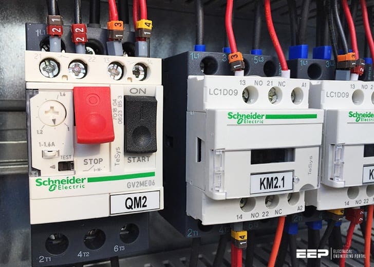 How do you know which current to set on a motor overload relay (photo credit: Edvard CSANYI, EEP)
Therefore, a current range is indicated on the motor’s nameplate. The exact current capacity can be calculated when we know the voltage.
Calculation example
When we know the precise voltage for the installation, the full-load current can be calculated at 254 Δ/440 Y V, 60 Hz. The data is indicated on the nameplate as shown on the illustration on below:
- f = 60 Hz
- U = 220-277 ∆/380 – 480 Y V
- In = 5.70 – 5.00/3.30 – 2.90 A
60 Hz data calculation:
- Ua = actual voltage 254 ∆/440 Y V (actual voltage)
- Umin = 220 ∆/380 Y V (Minimum values in the voltage range)
- Umax = 277 ∆/480 Y V (Maximum values in the voltage range)
UΔ = (UA – Umin) / (Umax – Umin)
which is in this case: UΔ = (254 – 220) / (227 – 220) = 0.6
UY = (UA – Umin) / (Umax – Umin)
which is in this case: UY = (440-380) / (480-380) = 0.6
So, UΔ = UY
Calculation of the actual full-load current (I)
Imin = 570/3.30 A
(Current values for Delta and Star at minimum voltages)
Imax = 500/2.90 A
(Current values for Delta and Star at maximum voltages)
Now, it is possible to calculate the full-load current by means of the first formula:
- I for Delta values: 5.70 + (5.00 – 5.70) × 0.6 = 5.28 = 5.30 A
- I for Star values: 3.30 + (2.90 – 3.30) × 0.6 = 3.06 = 3.10 A
The values for the full-load current correspond to the permissible full-load current of the motor at 254 ∆/440 Y V, 60 Hz.
However if motors are designed with a service factor, which is then shown on the nameplate eg. 1.15, the set current for the overload relay can be raised by 15% compared to full-load current or to the service factor amps (SFA) which is normally indicated on the nameplate.
If the motor is connected in star = 440 V 60 Hz the overload relay then has to be set to 3.1 A.
Reference // The motor book by Grundfos
Related electrical guides & articles


Edvard Csanyi
Hi, I'm an electrical engineer, programmer and founder of EEP - Electrical Engineering Portal. I worked twelve years at Schneider Electric in the position of technical support for low- and medium-voltage projects and the design of busbar trunking systems.I'm highly specialized in the design of LV/MV switchgear and low-voltage, high-power busbar trunking (<6300A) in substations, commercial buildings and industry facilities. I'm also a professional in AutoCAD programming.
Profile: Edvard Csanyi

Exactly the information I needed to understand how to PROPERLY set my thermal overload relay on a variety of 1-phase and 3-phase electric motors. The inclusion of accounting for motor Service Factors is especially important in the real world of electric motors. Thank you for authoring this article.
Really,I need this excellent article
Nice article
5.7+(5.00-5.70)*0.6=5.28
Where has this 0.6 come from and what is it?
Good day
I am happy to know I can get assistance on your site.
I am doing a family portable water project….with a 230v 10 hp 50 amp motor for the pump.
Can you tell me the best amp setting for the contactor overload.
Regards
L Dacres
thank for your cooperation and I m glad to see it. i will see for future partnership .
How do I know the size of overload for a motor
Do you have diagram for relay
it is a good document.
I would like to have all the news about electrical engineering
It was very nice about. Automation knowledge congratulations
15 by 12 meters conference Hall Electrical piping and wiring.
95 Eden North Sunnyside pretoria
The above explanation is good . Normally , O/L replay is connected in one of the phase of delta connection in the starter panel. In case of high HP motor , we provided CT in 3 phase connection for current & voltage checking. In that case can we provide O/L Relay by using CTs in the main income of starter panel.
we can also check the actual current and set the overload relay.
always refer to the motor nameplate
Setting a pick up current for an overload relay is specified in any IEC standard
this only for 3phase how about single phase connection
Good explanation . Need specific value of current at which relay should trip the motor with 440V Y and 3.1A setting.
Also plz explain if overload setting is made at nominal current of motor, mentioned on nameplate . Then what is the use of 1.15 or 1.25 times rated current setting. Thanks
I WANT TO DOWNLOAD ELECTRICAL VIDEOS
THANK YOU SIR FOR THE EXPLANATION .I WANT TO KNOW IF THE FREQUENCY IS 50 HZ THEN CAN I USE THIS FORMULA? PLEASE GIVE ME THE ANSWER
THANK YOU
I need more diagrams about motor connections
Thank you for a good explanation. I have a couple of people I work with that believe if you have a fast acting overtemp relay, you dont need overloads. If it gets hot, it’s overloaded. Not very fast enough for lost phases or locked rotors. I am not sure if it’s even legal as the standard calls for overload fitted to motors over 370w. Has anyone here got a correct answer?
Dear Sullivan
Normally the Fast Acting O.T.R. have an embedded sensor(s) in the motor armature coils, suppose for some reasons these sensors are no more working, then your motor is not protected at all.
It’s preferable to use the usual Over Load protection mean as the “Main Protection One” and the F.A.O.T.R. as a “Backup”, in this case you realize a complete protection of your motor against the overload events.