
Estimated Study Time: 42 minutes
Current & voltage in power circuits
If the voltage or current in a power circuit are too high to connect measuring instruments or relays directly, coupling is made through transformers. Such measuring transformers are required to produce a scaled down replica of the input quantity to the accuracy expected for the particular measurement.
 Current Transformers In a Nutshell
This is made possible by the high efficiency of the transformer. During and following large instantaneous changes in the input quantity, the waveform may no longer be sinusoidal, therefore the performance of measuring transformers is important.
Many protection systems are required to operate during the transient disturbance in the output of the measuring transformers following a system fault. The errors in transformer output may delay the operation of the protection or cause unnecessary operations.
Therefore the functioning of such transformers must be examined analytically.
- Simple equivalent circuit of current transformer
- Current transformer connections (primary/secondary)
- Errors
- Composite Error
- Accuracy Limit Current of Protection Current Transformers
- Class PX Current Transformers
- CT Winding Arrangements
- Winding Arrangements
- Secondary Winding Impedance
- Secondary Current Rating
- Rated Short-Time Current
- Transient Response of a Current Transformer
- Harmonics During the Transient Period
- Test Windings
1. Simple equivalent circuit of current transformer
The transformer can be represented by the equivalent circuit of Figure 1, where all quantities are referred to the secondary side.
When the transformer is not 1/1 ratio, this condition can be represented by energizing the equivalent circuit with an ideal transformer of the given ratio but having no losses.
Voltage transformers are much like small power transformers, differing only in details of design that control ratio accuracy over the specified range of output. Current transformers have their primary windings connected in series with the power circuit, and so also in series with the system impedance.
The response of the transformer is radically different in these two modes of operation.
This technical article will explain all important aspects of current transformers in MV and HV measurement and protection applications.
2. Current transformer connections (primary/secondary)
The primary winding of a current transformer is connected in series with the power circuit and the impedance is negligible compared with that of the power circuit.
The power system impedance governs the current passing through the primary winding of the current transformer. This condition can be represented by inserting the load impedance, referred through the turns ratio, in the input connection of Figure 1 above.
This approach is developed in Figure 2, taking the numerical example of a 300/5A CT applied to an 11kV power system. The system is considered to be carrying rated current (300A) and the CT is feeding a burden of 10VA.

A study of the final equivalent circuit of Figure 2(c), taking note of the typical component values, reveals all the properties of a current transformer.
It can be seen that:
- The secondary current is not affected by change of the burden impedance over a considerable range.
- The secondary circuit must not be interrupted while the primary winding is energized. The induced secondary e.m.f. under these circumstances is high enough to present a danger to life and insulation.
- The ratio and phase angle errors can be calculated easily if the magnetizing characteristics and the burden impedance are known.
2.1 Errors
The general vector diagram applicable for voltage transformer (click to see it) can be simplified by omitting details that are not of interest in current measurement. Take a look at the Figure 3.
So, Is = Ip − Ie
where Ie is dependent on Ze, the exciting impedance and the secondary e.m.f. Es, given by the equation:
Es = Is (Zs + Zb),
where:
- Zs = the self-impedance of the secondary winding, which can generally be taken as the resistive component Rs only
- Zb = the impedance of the burden
2.1.1 Current or Ratio Error
This is the difference in magnitude between Ip and Is and is equal to Ir, the component of Ie which is in phase with Is.
2.1.2 Phase Error
This is represented by Iq, the component of Ie in quadrature with Is and results in the phase error Φ .
The values of the current error and phase error depend on the phase displacement between Is and Ie, but neither current nor phase error can exceed the vectorial error Ie. With a moderately inductive burden, resulting in Is and Ie approximately in phase, there is little phase error and the exciting component results almost entirely in ratio error.
A reduction of the secondary winding by one or two turns is often used to compensate for this.
For lower value burden or a different burden power factor, the error would change in the positive direction to a maximum of +0.7% at zero burden; the leakage reactance of the secondary winding is assumed to be negligible.
No corresponding correction can be made for phase error, but it should be noted that the phase error is small for moderately reactive burdens.
2.2 Composite Error
This is defined in IEC 61869 1 and 2 as the r.m.s. value of the difference between the ideal secondary current and the actual secondary current. It includes current and phase errors and the effects of harmonics in the exciting current.
The accuracy class of measuring current transformers is shown in Table 1 and Table 2.
Table 1 – Limits of CT error for accuracy classes 0.1 to 1.0
| Accuracy Class | % current | +/- Percentage current (ratio) error | +/- Phase displacement (minutes) | ||||||
| 5 | 20 | 100 | 120 | 5 | 20 | 100 | 120 | ||
| 0.1 | 0.4 | 0.2 | 0.1 | 0.1 | 15 | 8 | 5 | 5 | |
| 0.2 | 0.75 | 0.35 | 0.2 | 0.2 | 30 | 15 | 10 | 10 | |
| 0.5 | 1.5 | 0.75 | 0.5 | 0.5 | 90 | 45 | 30 | 30 | |
| 1 | 3 | 1.5 | 1.0 | 1.0 | 180 | 90 | 60 | 60 | |
Table 2 – Limits of CT error for accuracy classes 3 and 5
| Accuracy Class | % current | +/- current (ratio) error, % | |
| 50 | 120 | ||
| 3 | 3 | 3 | |
| 5 | 5 | 5 | |
2.3 Accuracy Limit Current of Protection Current Transformers
Protection equipment is intended to respond to fault conditions, and is for this reason required to function at current values above the normal rating.
Protection class current transformers must retain a reasonable accuracy up to the largest relevant current. This value is known as the ‘accuracy limit current’ and may be expressed in primary or equivalent secondary terms.
The ratio of the accuracy limit current to the rated current is known as the ‘accuracy limit factor‘. The accuracy class of protection current transformers is shown in Table 3.
Table 3 – Protection CT error limits for classes 5P and 10P
| Class | Current error at rated primary current (%) | Phase displacement at rated current (minutes) | Composite error at rated accuracy limit primary current (%) |
| 5P | +/-1 | +/-60 | 5 |
| 10P | +/-3 | – | 10 |
| Standard accuracy limit factors are 5, 10, 15, 20, and 30 | |||
Even though the burden of a protection CT is only a few VA at rated current, the output required from the CT may be considerable if the accuracy limit factor is high. For example, with an accuracy limit factor of 30 and a burden of 10VA, the CT may have to supply 9000VA to the secondary circuit.
Alternatively, the same CT may be subjected to a high burden.
For overcurrent and earth fault protection, with elements of similar VA consumption at setting, the earth fault element of an electromechanical relay set at 10% would have 100 times the impedance of the overcurrent elements set at 100%.
Although saturation of the relay elements somewhat modifies this aspect of the matter, the earth fault element is a severe burden, and the CT is likely to have a considerable ratio error in this case. Therefore it is not much use applying turns compensation to such current transformers.
It is generally simpler to wind the CT with turns corresponding to the nominal ratio.
The applied burden is the total of instrument and relay burdens. Turns compensation may well be needed to achieve the measurement performance. Measurement ratings are expressed in terms of rated burden and class, for example 15VA Class 0.5.
Protection ratings are expressed in terms of rated burden, class, and accuracy limit factor, for example 10VA Class 10P10.
2.4 Class PX Current Transformers
The classification of Table 3 is only used for overcurrent protection. Class PX is the definition in IEC 61869 for the quasi-transient current transformers formerly covered by Class X of BS 7626, commonly used with unit protection schemes.
Guidance was given in the specifications to the application of current transformers to earth fault protection, but for this and for the majority of other protection applications it is better to refer directly to the maximum useful e.m.f. that can be obtained from the CT.
See Figure 4 below.

Design requirements for current transformers for general protection purposes are frequently laid out in terms of knee-point e.m.f., exciting current at the knee-point (or some other specified point) and secondary winding resistance.
Such current transformers are designated Class PX.
2.5 CT Winding Arrangements
Several CT winding arrangements are used. These are described in the following sections.
2.5.1 Wound primary type
This type of CT has conventional windings formed of copper wire wound round a core. It is used for auxiliary current transformers and for many low or moderate ratio current transformers used in switchgear of up to 11kV rating.
2.5.2 Bushing or bar primary type
Many current transformers have a ring-shaped core, sometimes built up from annular stampings, but often consisting of a single length of strip tightly wound to form a close-turned spiral. The distributed secondary winding forms a toroid which should occupy the whole perimeter of the core, a small gap being left between start and finish leads for insulation.
Such current transformers normally have a single concentrically placed primary conductor, sometimes permanently built into the CT and provided with the necessary primary insulation.
In other cases, the bushing of a circuit breaker or power transformer is used for this purpose.
The effect is particularly pronounced when the core diameter has been made large to fit over large EHV bushings.

2.5.3 Core-Balance Current Transformers
Ring type is the most usual type of core-balance current transformer (CBCT). Cable is passing through the centre of CT and in that way forms the primary winding.
Core Balance Current Transformers (CBCT’s) are employed for providing earth leakage protection in a power system. They are different from normal protective and metering current transformers due to their performance requirement.
In insulated or compensated neutral networks, earth leakage currents are small and are, generally, much smaller than nominal load currents.
Such earth leakage currents should not be allowed to exist for long periods of time, since they eventually cause insulation failure on healthy phases and subsequently develop into phase-to-phase or double phase to earth faults.
cases will be able to take measures to switch the load over to other feeders and switch out the faulted circuits for repairs.
Exception to this rule are circuits which supply power to peat pits, ore mines, and similar loads where, in view of safety considerations, the protection system is designed to switch out the circuit in the event of occurrence of earth leakage.
CBCT’s are manufactured with one core and one secondary winding. The number of secondary turns does not need to be related to the cable/feeder rated current because no secondary current would flow under normal balanced conditions.
This allows the number of secondary turns to be chosen such as to optimize the effective primary pick up current. The choice of ratio should therefore be left to the manufacture to obtain the best possible results.
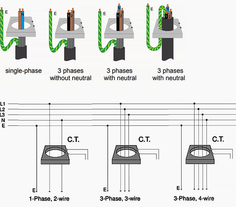
CBCT’s are used with suitable relays for earth leakage protection purposes. A CBCT encircles 3 Phases, 3-core cable or 3 single core cables.
During healthy conditions i.e. when there is no earth leakage current, the secondary of CBCT does not carry any current, as there is no net magnetic flux in the core.
In case an Earth Leakage occurs, a net unbalanced current sets up flux in the core of the CBCT and current flows through the secondary winding, causing the relay to operate. If more than one 3-phase cable are used in parallel, it is recommended that a separate CBCT on each cable be connected across a common relay or a separate relay be provided for each CBCT.
2.5.4 Summation Current Transformers
The summation arrangement is a winding arrangement used in a measuring relay or on an auxiliary current transformer to give a single-phase output signal having a specific relationship to the three-phase current input.
A typical ratio would be 5+5+5/ 5A, which means that three primary feeders of 5 are to be summated to a single 5A meter.

2.5.5 Air-gapped current transformers
These are auxiliary current transformers in which a small air gap is included in the core to produce a secondary voltage output proportional in magnitude to current in the primary winding.
Sometimes termed ‘transactors’ and ‘quadrature current transformers’, this form of current transformer has been used as an auxiliary component of traditional pilot-wire unit protection schemes in which the outputs into multiple secondary circuits must remain linear for and proportional to the widest practical range of input currents.
2.6 CT Winding Arrangements
CTs for measuring line currents fall into one of three types.
2.6.1 Over-Dimensioned CTs
Over-dimensioned CTs are capable of transforming fully offset fault currents without distortion. In consequence, they are very large. They are prone to errors due to remanent flux arising, for instance, from the interruption of heavy fault currents.
2.6.2 Anti-Remanence CTs
This is a variation of the over-dimensioned current transformer and has small gap(s) in the core magnetic circuit, thus reducing the possible remanent flux from approximately 90% of saturation value to approximately 10%. These gap(s) are quite small, for example 0.12 mm total, and so the excitation characteristic is not significantly changed by their presence.
Errors in current transformation are therefore significantly reduced when compared with those with the gapless type of core. Transient protection Current
Transformers are included in IEC 61869-2 as types TPX, TPY and TPZ and this specification gives good guidance to their application and use.
2.6.3 Linear Current Transformers
The ‘linear’ current transformer constitutes an even more radical departure from the normal solid core CT in that it incorporates an appreciable air gap, for example 7.5-10mm.
As its name implies the magnetic behaviour tends to linearization by the inclusion of this gap in the magnetic circuit.
Figure 10 shows a CT for use on HV systems.

2.7 Secondary Winding Impedance
As a protection CT may be required to deliver high values of secondary current, the secondary winding resistance must be made as low as practicable. Secondary leakage reactance also occurs, particularly in wound primary current transformers, although its precise measurement is difficult.
It is however, normally accepted that a current transformer is of the low reactance type provided that the following 4 conditions prevail:
- The core is of the jointless ring type (including spirally wound cores).
- The secondary turns are substantially evenly distributed along the whole length of the magnetic circuit.
- The primary conductor(s) passes through the approximate centre of the core aperture or, if wound, is approximately evenly distributed along the whole length of the magnetic circuit.
- Flux equalizing windings, where fitted to the requirements of the design, consist of at least four parallel-connected coils, evenly distributed along the whole length of the magnetic circuit, each coil occupying one quadrant.
Alternatively, when a current transformer does not comply with all of the above requirements, it may be proved to be of low-reactance. In this case the composite error, as measured in the accepted way, does not exceed by a factor of 1.3 that error obtained directly from the V-I excitation characteristic of the secondary winding.
2.8 Secondary Current Rating
The choice of secondary current rating is determined largely by the secondary winding burden and the standard practice of the user. Standard CT secondary current ratings are 5A and 1A.
The burden at rated current imposed by digital or numerical relays or instruments is largely independent of the rated value of current. This is because the winding of the device has to develop a given number of ampere-turns at rated current, so that the actual number of turns is inversely proportional to the current, and the impedance of the winding varies inversely with the square of the current rating.
However, electromechanical or static earth-fault relays may have a burden that varies with the current tapping used.
Interconnection leads do not share this property, however, being commonly of standard cross-section regardless of rating. Where the leads are long, their resistance may be appreciable, and the resultant burden varies with the square of the current rating.
For example a CT lead run of the order of 200 metres, a typical distance for outdoor EHV switchgear, could have a loop resistance of approximately 3 ohms. The CT lead VA burden if a 5A CT is used would be 75VA, to which must be added the relay burden (up to of perhaps 10VA for an electromechanical relay, but less than 1VA for a numerical relay), making a total of 85VA.
Such a burden would require the CT to be very large and expensive, particularly if a high accuracy limit factor were also applicable.
With a 1A CT secondary rating, the lead burden is reduced to 3VA, so that with the same relay burden the total becomes a maximum of 13VA. This can be provided by a CT of normal dimensions, resulting in a saving in size, weight and cost.
Hence modern CTs tend to have secondary windings of 1A rating. However, where the primary rating is high, say above 2000A, a CT of higher secondary rating may be used, to limit the number of secondary turns. In such a situation secondary ratings of 2A, 5A or, in extreme cases, 20A, might be used.
2.9 Rated Short-Time Current
A current transformer is overloaded while system short-circuit currents are flowing and is short-time rated. Standard times for which the CT must be able to carry rated short-time current (STC) are 0.25, 0.5, 1.0, 2.0 or 3.0 seconds.
A CT with a particular short-time current/ time rating carries a lower current for a longer time in inverse proportion to the square of the ratio of current values.
The converse, however, cannot be assumed, and larger current values than the STC rating are not permissible for any duration unless justified by a new rating test to prove the dynamic capability.
2.10 Transient Response of a Current Transformer
When accuracy of response during very short intervals is being studied, it is necessary to examine what happens when the primary current is suddenly changed.
2.10.1 Primary Current Transient
The power system, neglecting load circuits, is mostly inductive, so that when a short circuit occurs, the fault current that flows is given by:
where:
- Ep = peak system e.m.f.
- R = system resistance
- L = system inductance
- β = initial phase angle governed by instant of fault occurrence
- α = system power factor angle = tan−1 ωL/R
The first term of Equation 6.1 represents the steady state alternating current, while the second is a transient quantity responsible for displacing the waveform asymmetrically.
ip is the steady state peak current:
The maximum transient occurs when sin (α − β) and no other condition need be examined. So:
When the current is passed through the primary winding of a current transformer, the response can be examined by replacing the CT with an equivalent circuit as shown in Figure 2(b).
The flux developed in an inductance is obtained by integrating the applied e.m.f. through a time interval:

For the CT equivalent circuit, the voltage is the drop on the burden resistance Rb. Integrating for each component in turn, the steady state peak flux is given by:

The transient flux is given by:
Hence, the ratio of the transient flux to the steady state value is:
where X and R are the primary system reactance and resistance values. The CT core has to carry both fluxes, so that:
Alternatively, L/R is the primary system time constant T, so that the transient factor TF can be written:
Again, fT is the time constant expressed in cycles of the a.c. quantity T’ so that:
![]()
This latter expression is particularly useful when assessing a recording of a fault current, because the time constant in cycles can be easily estimated and leads directly to the transient factor.
The above theory is sufficient to give a general view of the problem.
In this simplified treatment, no reverse voltage is applied to demagnetize the CT, so that the flux would build up as shown in Figure 11.

Since a CT requires a finite exciting current to maintain a flux, it does not remain magnetized (neglecting hysteresis), and for this reason a complete representation of the effects can only be obtained by including the finite inductance of the CT in the calculation.
The response of a current transformer to a transient asymmetric current is shown in Figure 12 below.

Let:
- is = the nominal secondary current
- i’s = the actual secondary output current
- ie = the exciting current
then:
is = ie + i’s
also,

where:
which gives for the transient term:
where:
- T = primary system time constant L/R
- T1 = CT secondary circuit time constant Le/Rb
- I1 = prospective peak secondary current
2.10.2 Practical Conditions
Practical conditions differ from theory for the following reasons:
Reason #1
No account has been taken of secondary leakage or burden inductance. This is usually small compared with Le so has little effect on the maximum transient flux.
Reason #2
Iron loss has not been considered. This has the effect of reducing the secondary time constant, but the value of the equivalent resistance is variable, depending upon both the sine and exponential terms.
Consequently, it cannot be included in any linear theory and is too complicated for a satisfactory treatment to be evolved.
Reason #3
The theory is based upon a linear excitation characteristic. This is only approximately true up to the knee-point of the excitation curve.
A precise solution allowing for non-linearity is not practicable.
Reason #4
The effect of hysteresis, apart from loss as discussed under (Reason #2) above, is not included. Hysteresis makes the inductance different for flux build up and decay, so that the secondary time constant is variable.
A precise calculation of the flux and excitation current is not feasible. The value of the study is to explain the observed phenomena.
The asymmetric (or d.c.) component can be regarded as building up the mean flux over a period corresponding to several cycles of the sinusoidal component, during which period the latter component produces a flux swing about the varying ‘mean level’ established by the former. The asymmetric flux ceases to increase when the
exciting current is equal to the total asymmetric input current, since beyond this point the output current, and hence the voltage drop across the burden resistance, is negative.
Saturation makes the point of equality between the excitation current and the input occur at a flux level lower than would be expected from linear theory.
When the exponential component drives the CT into saturation, the magnetizing inductance decreases, causing a large increase in the alternating component ie.
The total exciting current during the transient period is of the form shown in Figure 13 and the corresponding resultant distortion in the secondary current output, due to saturation, is shown in Figure 14.

The presence of residual flux varies the starting point of the transient flux excursion on the excitation characteristic.
Remanence of like polarity to the transient reduces the value of symmetric current of given time constant which the CT can transform without severe saturation. Conversely, reverse remanence greatly increases the ability of a CT to transform transient current.
If the CT were the linear non-saturable device considered in the analysis, the sine current would be transformed without loss of accuracy.
The output current is reduced during transient saturation, which may prevent the relays from operating if the conditions are near to the relay setting. This must not be confused with the increased r.m.s. value of the primary current due to the asymmetric transient, a feature which sometimes offsets the increase ratio error.
In the case of balanced protection, during through faults the errors of the several current transformers may differ and produce an out-of-balance quantity, causing
unwanted operation.
2.11 Harmonics During the Transient Period
When a CT is required to develop a high secondary e.m.f. under steady state conditions, the non-linearity of the excitation impedance causes some distortion of the output waveform. In addition to the fundamental current, such a waveform contains odd harmonics only.
However, when the CT is saturated unidirectionally while being simultaneously subjected to a small a.c. quantity, as in the transient condition discussed above, the output contains both odd and even harmonics.
Usually the lower numbered harmonics are of greatest amplitude and the second and third harmonic components may be of considerable value. This may affect relays that are sensitive to harmonics.
2.12 Test Windings
On-site conjunctive testing of current transformers and the apparatus that they energize is often required. It may be difficult, however, to pass a suitable value of current through the primary windings, because of the scale of such current and in many cases because access to the primary conductors is difficult.
Additional windings can be provided to make such tests easier and these windings are usually rated at 10A.
The test winding inevitably occupies appreciable space and the CT costs more. This should be weighed against the convenience achieved and often the tests can be replaced by alternative procedures.
Sources //
- Network protection and automation guide by (ex) Alstom Grid, now General Electric
- Core-balance current transformer by Loreme
- Core-balance current transformer by Gilber and Maxwell transformers
- Electric Power Substations Engineering By James C. Burke
Related electrical guides & articles


Edvard Csanyi
Hi, I'm an electrical engineer, programmer and founder of EEP - Electrical Engineering Portal. I worked twelve years at Schneider Electric in the position of technical support for low- and medium-voltage projects and the design of busbar trunking systems.I'm highly specialized in the design of LV/MV switchgear and low-voltage, high-power busbar trunking (<6300A) in substations, commercial buildings and industry facilities. I'm also a professional in AutoCAD programming.
Profile: Edvard Csanyi

What happens if the Protection CT selected are too high/large in Ratio. The Feeder current in actual is 12 Amps at 33kV. However the Vendor ABB have provided the CT’s with Ration of 200/1 for REF615 Protection Relay.
In Figure 2 (c) It says referred to Secondary side but I think it looks like it is actually referred to the Primary side?
If you were referring to the Secondary side, wouldn’t you be dividing Zr by the turns ratio a^2 (i.e. divide by 60) and not multiply by 60?
i really likethis program it is intersting becuase i am a 14 year old who likes electrical engineering
In fig 2 a and 2b it is not clear how 6350 V appears across the primary terminal of the current transformer. Could you pls elaborate as I understand the primary winding is in series with voltage source and by virtue of the low impedance of the primary winding, voltage across it is expected to be low as per voltage divider rule?
Thank you for the excellent article.
HI Thank you for your content
I know little
please if may send content from high-voltage power stations such as tests
Excellent topic on CT’s
Dear Edvard Csanyi
can you describe VCB panel and ACB Panel for 0.5 MVA Sub-station , I mean proper equipment and their ideal ratings.
thanks..
Great article,very informative.
CT ratio 100/5 explore like capicter. Its possible
dear sir i am manufacturer of handmade ct,s so i want to buy a book on ct please suggest me how i can purchase book in india with different ct,s
Excellent topic about CTs.
This subject is good & also the demonstration but no figures appeared which make little difficulties to get full understanding.
Please attach the figures
thanks you
omara
It’s fixed, should be fine now.
Very nice article, thanx