Overvoltage problems and prevention
Electric insulation in energized systems is continuously under stress. Electric systems are subject to disturbances of many types which unavoidably produce overvoltages. However, the application engineer has at his command many system design principles which will greatly curb the magnitude of overvoltages.

It is important to note that AC systems are subject to many types of overvoltages not to be found in DC systems; hence AC systems deserve more careful consideration of the overvoltage problem.
Overvoltage sources
There are many varied sources of overvoltages of sufficient magnitude to be damaging to the insulation of AC industrial power distribution systems. In this article, the mechanism by which the more prominent overvoltages are created will be described and preventative measures suggested.
Treatment of the following will be included:
- Static overvoltage
- Physical contact with a higher voltage system
- Resonance effects in series inductive-capacitive circuits
- Repetitive intermittent short circuits
- Switching surges
- Forced zero-current interruption
- Autotransformer connections
- Lightning
Of these, most are the result of effects directly within the electric system itself. In contrast, lightning (a vicious source of an overvoltage) is communicated to the electrical system from nature’s powerhouse in the heavens above.
1. Static overvoltage
Wind-blown sand or dust can become highly charged and impart relatively high voltage to exposed overhead electric conductors. Moving belts running on non-metallic pulleys can also develop high voltages by static means which may, in turn, be communicated to electric system conductors if electric enclosing frames arc improperly grounded.
In addition to grounding the electric service system, it is important that electric machine frames and all metallic enclosures which contain electric circuit conductors be effectively grounded (see article below).
Suggested Course – Earthing and Grounding in Power Systems: Calculations, Design and Measurements
Earthing and Grounding in Power Systems: Calculations, Design and Measurements
Go back to the Contents Table ↑
2. Physical contact with a higher voltage system
If the conductors of a high-voltage electrical circuit come in contact with those of a lower voltage circuit, then the same potential will exist on both circuits at the point of contact. If the low-voltage circuit does not have its neutral grounded, its potential will be increased to that of the high-voltage system or flashover will occur.
If the low-voltage system is anchored close to ground potential as by the use of a solidly grounded neutral, high values of current may flow from the high-voltage system, but a much lower voltage will appear than with an isolated neutral system.
Occasional cross-ups have occurred between primary and secondary on overhead circuits, and a few cases are known where failure has occurred between primary and secondary inside a transformer.
Figure 1 – Overvoltage on 480V ungrounded system resulting from contact with a higher voltage system
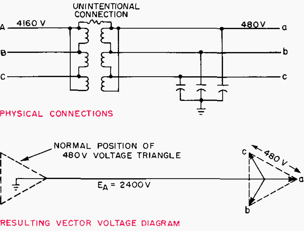

Figure 1 illustrates this type of fault connection. It can be responsible for dangerous overvoltages on ungrounded low-voltage systems.
The most effective protection against that type of overvoltage is grounding of the low-voltage system with the grounding impedance made low enough to accept the maximum line-to-ground fault current of the high-voltage system without biasing the neutral of the low-voltage system by a dangerous amount.
Go back to the Contents Table ↑
3. Resonance effects in series inductive-capacitive circuits
(Limited to AC systems)
Ungrounded-neutral AC systems are most commonly subject to overvoltages originating from this cause. It is important to recognize that ungrounded-neutral systems are actually capacitively coupled to the ground rather than truly divorced from the ground.
Every ungrounded electric system contains the essential elements presented in the diagram of Figure 2. The electrical behaviour of any single-phase conductor relative to the ground can be determined by a much simpler equivalent circuit, as indicated in the lower sketch of Figure 2.
Figure 2 – Elemental composition of an ungrounded system
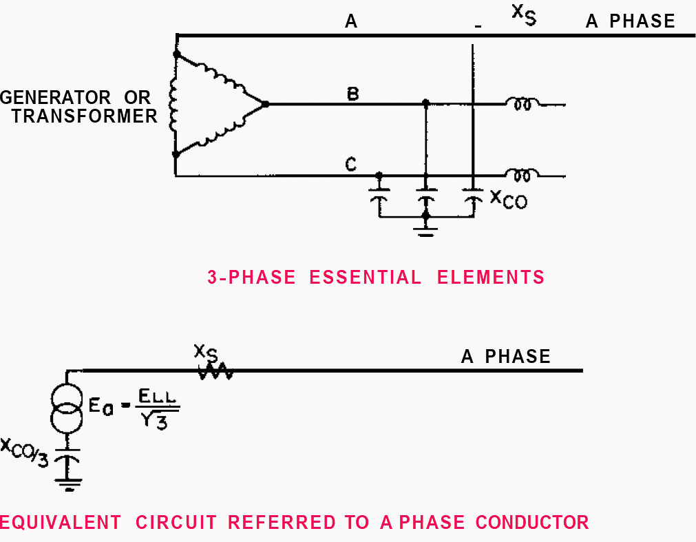

In terms of this simpler equivalent circuit, it will be possible to understand readily the effect of connecting different types of impedance between line and ground as shown in Figure 3. It becomes evident that the connection of any value of either resistance or capacitance between a single line and the ground produces no dangerous overvoltages.
The potential on the phase to which the impedance is connected progressively diminishes from a normal value to zero. The potential to the ground on the remaining two phase conductors will be increased to full line-to-line value at the time the first phase conductor has been reduced to zero potential.
This represents an overvoltage of only 73%, which is not dangerously high and will normally produce no dangerous effect unless continued for a long time.
The highest overvoltage will occur when these two reactances are equal, and at this point, they may be as much as ten times normal. It is significant to note, however, that over a two-to-one range of reactance, overvoltages of three times normal or more would be produced.
Figure 3 – Overvoltages on ungrounded systems resulting from a high-inductive-reactance connection between line and ground


The unintentional connection of an inductive reactance between a phase conductor and ground can occur in a number of ways, some of which are illustrated in Figure 4. The operating magnetic coil of a motor starter contactor may be inadvertently connected between phase and ground by a ground short circuit in the control wire to the push-button station or the slip of a maintenance man’s screwdriver.
Any time that the inductive-reactance value (which becomes connected from phase to ground) falls in the danger region indicated in Figure 3, dangerous overvoltages to the ground will be produced which are communicated over the entire metallic conductor system of that operating voltage.
Overvoltages originating from this case can be completely suppressed by a relatively light-resistance ground on the electric system neutral.
Figure 4 – Examples of unintentional high-reactance connections between line and ground (click to zoom)


A grounding resistor of about the same ohmic value as the total charging capacitive reactance to the ground is sufficient to eliminate overvoltages almost completely. It will be evident that there is good reason to adopt electric system neutral grounding with a much lower value of grounding resistance for other reasons.
Figure 3 has been computed on the basis that the inductive reactance is linear. If this reactance incorporates an iron core which during the mode of operation being considered should encounter magnetic saturation, the performance will be somewhat different. Under such conditions, the effective reactance of the inductive circuit can become much lower than the unsaturated reactance, and the voltage will tend to oscillate automatically between voltage limits which cause the effective inductive reactance to match the capacitive-reactance value.
This character of operation has been named ferroresonance (see a case study). The maximum voltage so developed may not be so high as would be produced by a linear reactor but, may still be in excess of two or three times normal. Substantial overvoltages may result from ferroresonance when the unsaturated reactance is many times the capacitive reactance to the ground.
These system voltage oscillations will not occur if the electric system neutral is grounded. Freedom from this particular type of voltage oscillation can be obtained even with ungrounded-neutral operation by using potential transformers with a line-to-line voltage rating and the application of shunting resistors on the secondary windings as is outlined in Figure 5.
Figure 5 – Grounded-Y broken delta potential transformers for a ground indicator or zero-sequence voltage detector
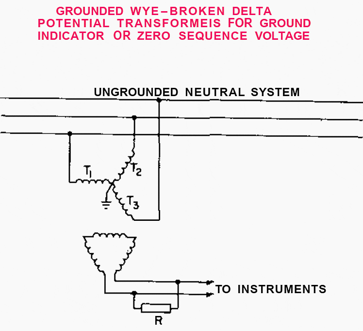

To ensure freedom from unwanted line-to-ground ground voltage oscillations:
- Select PTs T1, T2 and T3, with the line-to-line rated voltage
- Apply a secondary loading resistor with a resistance not greater than 40% of the transformer magnetizing reactance.
Important Note – The loading resistance can be applied to each secondary but will then consume power and liberate heat continuously (Learn more).
Series-capacitor melders are occasionally applied, particularly in the case of large-size machines because of their ability to reduce the kVA demand and improve the operating power factor to substantially unity.
However, the series-capacitor welder presents a definite voltage hazard to an ungrounded-neutral AC supply system. During welder operation, the voltage across both the series capacitor and the welding transformer primary will be several times the rated line-to-line voltage. The physical electric connections and the associated vector voltage relationships are indicated in Figure 6 below.
Figure 6 – Overvoltages on ungrounded systems as a result of o ground contact on a series capacitor welding machine


Should a fault to ground occur at the junction between the series capacitor and the welding transformer (point P), the location of ground potential will tend to become that of this junction point instead of the centre of the AC system voltage triangle.
In the case illustrated in Figure 6, it will be evident that the potential of the A-phase conductor may be elevated to about 2000 V to ground, which is about seven times normal. As in the other cases, this overvoltage is communicated to all equipment metallically interconnected at this common operating voltage.
All these resonant inductive-capacitive overvoltage hazards can be eliminated by electric system neutral grounding.
Go back to the Contents Table ↑
4. Intermittent ground faults
Substantial overvoltages can be developed in ungrounded AC industrial systems by sputtering or intermittent ground-faulting connections. The intermittent character of the short-circuit path may be the result of:
- Vibration which causes an electrical conductor to make contact intermittently with the ground,
- Scattering particles of molten conductor metal which intermittently establishes a conducting path to ground, or
- Successive breakdown and seal off of the separating space between conductor and ground.
In the last case involving a fixed separation between conductor and ground, a progressively increasing breakdown voltage across this gap is an essential element in the build-up of severe overvoltages.
Intermittent ground-fault conditions on low-voltage ungrounded-neutral systems have been observed to create overvoltages of five or six times normal quite commonly. An unusual case involved a 480 V ungrounded system. Line-to-ground potentials in excess of 1200 V were measured on a test voltmeter. The source of trouble was finally traced to an intermittent ground fault in a motor-starting autotransformer.
About two hours elapsed while the source was being located, during which time between 40 and 50 motors broke down.
In Figure 7, at A is shown the vector voltage pattern of a three-phase AC system as it would operate under normal balanced conditions. The voltage vectors Ea, Eb, and Ec rotate about the neutral at synchronous speed. The electric neutral is a point of central symmetry and remains constant at ground potential if the individual phase voltages are pure fundamental-frequency sine waves.
Figure 7 – Overvoltages on ungrounded systems due to repetitive momentary contact between one line and ground
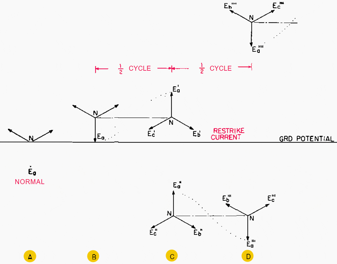

Should the A-phase conductor become grounded, the system voltage triangle would become displaced as illustrated in B. At the phase position illustrated in B, the A-phase voltage is at its maximum value at which instant the charging current to ground (90° ahead of the voltage) is passing through zero.
In case the short circuit contains a small gap or an arc, the arc current would become extinguished at this point. Note that the trapped charge on the line-to-ground capacitance will tend to maintain the voltage triangle in the same displaced position. In other words, the potential of the neutral (relative to ground) would tend to remain at a DC potential equal to the crest value of the a-c voltage wave.
All this merely says that there will be little tendency for any voltage to reappear across the gap in the short circuit immediately following the current zero which occurs at B.
During the next half-cycle, however, the AC generated voltages will reverse their polarities (vectors rotate 180°), which would cause the three-phase vector voltage pattern to assume the position shown in the upper part of C.
Inevitably there will be some system reactance in the A-phase conductor to the ground short-circuit point which would result in an oscillation of the A-phase-conductor potential between +2 and −2 at a frequency probably 20 to 100 times normal. If the short circuit consisted of a solid metallic connection, this oscillation would decay to zero, leaving the A-phase conductor at ground potential.
Note that associated with this high-frequency transitory oscillation will be a corresponding transitory charging current to the ground.
This transitory charging current to ground, or restrike current, will again reach zero value when the system voltage swing is at the maximum excursion in the negative direction, as shown in the lower part of C.
Suggested Course – Learn to Read and Analyze Circuit Breaker Schematics and Control Wiring Diagrams
Learn to Read and Analyze Circuit Breaker Schematics and Control Wiring Diagrams
Go back to the Contents Table ↑
5. Switching Surges
Circuit switching operations constitute abrupt changes in circuit parameters and can be responsible for the creation of overvoltages although generally of short duration and not in excess of two to three times normal. It will be important to recognize that normal AC switching interrupters
offer very little opposition to the flow of circuit current during the course of current flow but do act to build up dielectric strength rapidly during a normal current zero and prevent reestablishing current flow during the following half cycle.
As a result of this action, it is unnecessary that the stored magnetic energy in the inductance of the circuit is disposed of during interruption.
Interruption takes place at a normal current zero, at which time the stored magnetic energy is zero. A qualitative understanding of the mechanism whereby such overvoltages are generated will be useful.
With the vector relationships shown in the figure, the current in the faulted circuit will be going through zero, which affords an opportunity for the circuit breaker to make an interruption if the contacts have parted.
If the current flow is interrupted at this current zero, the potential of a’ tends to return to ea while that of point b’ tends to return to eb.
Figure 8 – Overvoltages due to interruption of line-to-line short circuit at current zero


There will inevitably be inductive capacitive constants that cause this return to take the form of an oscillation of relatively high frequency. This causes the potential of points a’ and b’ to overshoot their final value by about an equal amount.
In this illustrative example, the potential of point b’ would transitorily swing to a value of 1.73 times normal crest voltage in the positive direction while that of the point a’ would make a corresponding swing to 1.73 times normal crest value in the negative direction.
Another form of switching transient which develops overvoltage primarily on the utilization machine on contact closing is illustrated in Figure 9.
Here illustrated is an open-cycle autotransformer starting arrangement. It has been assumed that 65% voltage has been applied on the starting connection and the machine rotor brought up to near synchronous speed. The motor was then disconnected from the starting tap preparatory to reconnection across full-line voltage.
During this interval, it is possible that the internally generated voltage within the motor has dropped to 50% of the rating and has slipped back in angle so as to be 180° out of phase with respect to the supply system.
Figure 9 – Possible switching overvoltage when motor running breaker closes open-cycle autotransformer start


At this point, the potential difference appearing across each of the three line-switching contacts is one and a half times normal line-to-neutral voltage as indicated by the vector relationships. Suppose that the line-switching unit is now closed and that pole 1 is the first to make contact. The potential of motor terminal R would tend to abruptly assume the potential ea but the inevitable transitory overshoot would carry it on up to 250% normal with respect to ground.
The potential of the motor terminals A and C would tend to be carried along and suffer a transitory excursion to 325% voltage with respect to ground unless contacts 2 and 3 close at almost the same instant as contact 1. Closed-cycle starting arrangements such as reactor starting or Korndörfer autotransformer starting to minimize the overvoltages which may be developed in this manner.
One of the most severe sources of switching overvoltages is associated with the separation of two system sections which have become unsynchronized and are switched apart when the generated voltages in the two sections are nearly 180° out of phase. The elements of this case are illustrated in Figure 10, which shows a synchronous motor that has pulled out of step and the internally generated voltage of which is 180° out of phase with respect to the system.
The main supply system on the left is considered to be operating with grounded neutral and contains a much smaller reactance than the motor circuit shown on the right. All three poles of the switching interrupter have been maintained in a closed position up to the time indicated by the vector diagram.
Figure 10 – Possible overvoltages when interrupting the synchronous motor during out-of-step conditions


It has been assumed that, in the course of pull-out operation, the demagnetizing reactive current which has been flaming in the motor stator windings has caused the internally generated voltage ahead of transient reactance in the motor to be depressed to 50% of normal value. With the vector system in the position shown, the current in the A-phase is going through zero, which affords an opportunity for interruption if the contacts have parted.
If the current in the A-phase conductor is interrupted at this point, the potential of the motor A-phase terminal (point a2)will tend to jump to the right to its new steady-state position EA.
The inevitable transitory overshoot will cause its potential to swing about an equal distance to the other side of point EA, as shown by the dotted line. At the maximum of this transitory excursion, the potential of point a2 would reach about 3% times the normal crest to the ground in the positive direction.
Arc-furnace circuits can be sources of rather a severe overvoltage if switched off while an arc is in progress within the furnace. As the primary circuit-breaker contacts part, current at the breaker contacts can be forced to zero while current still continues to flow in the furnace arc.
Suggested Reading – MV/HV switchgear (circuit breaker) switching capability and suitability for specific applications
MV/HV switchgear (circuit breaker) switching capability and suitability for specific applications
Thus the circuit breaker accomplishes an interruption of line current with current flow still continuing in the secondary circuit. As the furnace internal current diminishes, the potential across the furnace arc increases in accordance with the normal inverse volt-ampere characteristic of an arc. The arc voltage progressively increases as the current diminishes and can result in a substantial voltage drop as the arc snaps out.
While this voltage may not be high as referred to in the arc-furnace anode, it still may be many times normal operating voltage and will be reflected to the primary side of the transformer by the turn ratio.
The voltage developed at the transformer high-tension terminals may be dangerously high and sufficient to produce flashover.
Go back to the Contents Table ↑
6. Forced-current-zero interruption
The discussion of switching overvoltages so far has considered interruption only at a normal current zero. The term forced current zero or interruption of current zero is used to describe an interrupting mechanism (be it a fuse, switch, section of small wire conductor, etc.) that has the property of developing a large counter voltage in opposition to current flow which can force current to zero value at a time quite different from the normal inherent current zero of the circuit.
Should any element in an electric circuit have the ability to develop a high potential drop during current flow, the potential so developed would appear on connected circuit conductors. The overvoltages so developed would persist until the stored energy in the inductive elements of the circuits has been dissipated (a current zero has been forced).
The total voltage drop across the entire section of the conductor may be several times the normal operating voltage of the circuit. During this interval of overvoltage, the magnitude of the current is being diminished; however, the overvoltage will persist until the magnitude of current has been returned to zero value.
Suggested Reading – Dos and don’ts in operating LV/MV circuit breakers, relays, disconnectors and fuses
Dos and don’ts in operating LV/MV circuit breakers, relays, disconnectors and fuses
Because of the overvoltage problems, the vacuum contact switch finds little application. The vacuum switch tends to instantly shut off the current completely that the contacts part. Unless suitable overvoltage suppressors are associated with such an interrupter, high voltages will be developed if applied in inductive circuits. The overvoltages so produced may be sufficient to spark over the outside of the vacuum switch unless some other portion of the circuit breaks down at a lower voltage.
Current-limiting fuses constitute an example of a forced current interrupter. They possess the property of being able to reduce the current to zero value ahead of a normal current zero. Overvoltages are developed during the operation of such an interrupter.
Go back to the Contents Table ↑
7. Autotransformer connections
Autotransformers for interconnecting two electric systems of different insulation levels should be avoided in industrial systems unless both are solidly neutral grounded. The common metallic interconnection between the two systems which is formed by the autotransformer windings tends to subject the lower voltage system to nearly the same transitory voltages as would be expected on the higher voltage system.
There are some exceptions, and a specific example will serve to illustrate nature.
Should a system be planned which is to operate initially at 2400 V and later be converted to 4160 V with all equipment therein containing insulation levels commensurate with 4100 V operating potential, it would be satisfactory to employ a suitable autotransformer for interconnecting this 2400V system with another 4160 V system.
An unusual variation of autotransformer action which has been responsible for system overvoltages in a number of instances is represented by a transformer with extended windings operating on an ungrounded-neutral system such as illustrated in Figure 11.
If operated with system line voltage impressed across a fraction of the total winding, the vector voltage at the end of the winding extension will be as illustrated in Figure 11 because the volts per turn developed in the winding extension will be exactly the same as the volts per turn in the excited winding.
Figure 11 – Overvoltage on ungrounded systems due to a ground connection on the winding extension of an autotransformer


Should the end of the winding extension be inadvertently connected to ground or develop a short circuit to ground, the point of ground potential would tend to move away from the centre of the voltage triangle to the potential of the extreme end of the winding extension resisted only by the high system-to-ground capacitance coupling.
It will be evident that, as a result of this action, the presence of any extended winding would cause the potential of one phase conductor to be elevated to more than 173% of normal operating potential.
As has been true so many times before, grounding of the electric supply system-neutral will cure this type of potential overvoltage also.
A system grounding equipment that makes available a ground-fault current that is equal to or greater than the short-circuit current resulting from the short circuit of the extended winding portion of the offending transformer will keep the system line-to-ground potentials within safe bounds. It is quite generally true that transformers of this character to be found in test areas are of relatively small physical size and do not impose restrictive requirements on the necessary system grounding equipment.
As a matter of fact, on all low-voltage-system equipment (600 V and less) it is the standard practice to ground the neutral solidly.
Suggested Course – Electrical Transformer Theory, Design, Construction, Protection and Maintenance
Electrical Transformer Theory, Design, Construction, Protection and Maintenance
Go back to the Contents Table ↑
8. Lightning
The highest overvoltages to which industrial power systems are subjected are those caused by lightning. Limiting these overvoltages by suitable protective measures is essential if costly equipment failures and service interruptions are to be avoided.
Nature of the overvoltages
A lightning stroke to earth represents the sparkover of a highly charged condenser, a cloud forming one plate, the earth the other, and the air between the dielectric. The initial charge has been estimated to be as high as 1 billion volts, and stroke currents as high as 200,000 amp have been measured.
Direct Strokes and Induced Surges
Lightning may produce an overvoltage on a transmission line either by a direct stroke to the line or by electrostatic induction from a stroke to earth in the vicinity of the line. The probable maximum voltage appearing on a line by a direct stroke is 15 million volts and for an induced surge, 500,000 volts.
These voltages appear between conductor and ground.
Suggested Reading – 5 most important aspects of external protection against the effects of lightning
5 most important aspects of external protection against the effects of lightning
Wave Shapes
Although the voltage surges produced by lightning have high magnitudes, their duration is very short. It is measured in microseconds (millionths of a second). Typically, the voltage rises very rapidly (in 1 to 10psec) to the maximum or “crest,” value and then decays more slowly, reaching 50% of the crest value in 20 to 150 psec.
As illustrated in Figure 12, the shape of a voltage or current, surge produced by lightning (and those produced artificially for test purposes) is
customarily expressed by two numbers.
Figure 12 – Terms ured to describe voltage and current waves
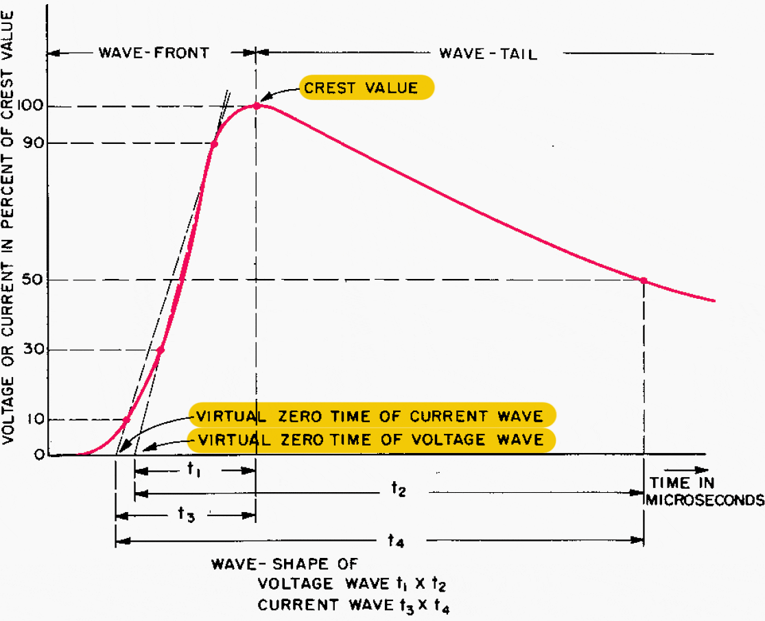

The first is the time from the “virtual zero” of the wavefront to the time the wave reaches the crest value, while the second number is the time from the virtual zero to the time the voltage or current has decreased to 50 per cent of the crest value. The virtual zero of a wavefront is the intersection with the zero axis of a straight line drawn through the points on the front of the wave which are 30% and 90% of the crest value for a voltage wave and 10% and 90% of crest value for a current wave.
Both times are usually expressed in microseconds. To illustrate, a 95 kV 1½ × 40 psec wave is one that has a crest value of 95 kV, rises to crest value in 134 psec from the time of virtual zero, and decays to 50% of crest value (47.5 kV) in 40 psec from the time of virtual zero.
Travelling Waves
The voltage surge produced on a transmission line by lightning does not appear simultaneously at all points on the line; instead, it appears at successively later intervals of time as the distance from the point of the stroke increases. Furthermore, the magnitude and shape (voltage vs. time) of the surge remain approximately the same at all points of a uniform line but are simply displaced in the time phase.
Neglecting all resistances, it can be shown that:
- The voltage waves travel along the conductor without change in magnitude or shape with a velocity equal to 1/√LC fps, where L is the inductance in Henrys per foot of line and C is the capacitance in farads per foot of line.
- A current wave accompanies the voltage wave and is of exactly the same shape, that is, at any instant at any point on the line, the current flowing in the conductor is directly proportional to the voltage from conductor to ground.
- The constant of proportionality between the current and voltage is called the surge impedance Z and is equal to √LC ohms, where L is the inductance in henrys for any unit length of the line and C is the capacitance in farads for the same unit length. The current in amperes is equal to the voltage in volts divided by the surge impedance in ohms.
The inductance and capacitance of an overhead line are such that the velocity of a current or voltage wave (called the velocity of propagation) is equal to the velocity of light in free space, which is 984 ft per psec. In most calculations, the round number 1000 is used.
The propagation velocity in a cable varies with its construction, but a typical value is 600 ft per psec.
Go back to the Contents Table ↑
Source: Industrial power systems by D. Beeman


