
Estimated Study Time: 51 minutes
How To: Digital substations and IEDs
Digital substations are pretty fragile in terms of various kinds of threats. Yes, they are advanced and have a vast number of highly effective protection and control features, but this time, we’ll talk about the threats that can possibly compromise the operation of a modern digital substation, especially Intelligent Electronic Devices (so-called IEDs).
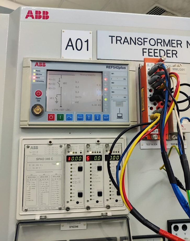 Dangerous threats that can compromise operation of modern digital substations and IEDs (on photo: REF 542plus feeder terminal - a compact digital bay control used for feeder protection, transformer protection and motor protection. It combines measurement, monitoring, protection, control and self diagnostics; credit: Muhammed Sahadh)
It is not the same whether the substation was built from scratch to be digital or if an old (possibly analog) substation was upgraded. The difference could be drastic.
This technical article provides an introduction to the properties of Intelligent Electronic Devices (IEDs) that are utilized for control and monitoring purposes. Additionally, it provides a brief description of some phenomena that have the potential to negatively impact the physical and functional integrity of such devices.
However, let’s say a word as an introduction to the subject.
IEC 61850 standards define the bay level as an intermediate control place between the switchgear boards and the main control house of the substation. The bay level is located between the two types of control places. At this level, the control, monitoring, and other essential duties are carried out from one of the many local control rooms that are situated within the switchyard.
Copper wiring or a newly developed network configuration known as the process bus are the means by which IEDs interact with primary equipment that has been installed at the switchyard.
This article discusses the components of the bay level as well as the measures to assure survival in the environment that can be found around them.
- Environmental and Operational Considerations:
- Insulation Considerations in the Secondary System
- Switchyard Control House
- Design of Control Cubicles:
- The Bay Control Unit (BCU)
- Other Bay Level Components
- Process Bus (Copper Wiring Free)
- Dangerous Trends in the Development of Relay Protection Equipment
- BONUS (PDF) 🔗 Download Guidance For Commissioning Of Electric Power Systems
1. Environmental and Operational Considerations
Substation equipment and all electrical devices are vulnerable to destructive natural occurrences like lightning strikes and seismic activity, as well as to intense transient waves and other electromagnetic disruptions caused by events like the switching of reactive loads and insulation faults between phases and the earth.
These facts highlight the imperative for substation engineers to comprehend the theoretical foundation of specific phenomena and their potential impact on substation components.
1.1 Lightning Strike
A lightning strike is a massive discharge of electric energy that travels from a cloud to the Earth’s surface, often occurring between clouds as well. This discharge releases an immense amount of energy within a very short period of time, typically lasting only a few milliseconds. This phenomena leads to a maximum discharge of direct current (DC) with a potential of 50,000 A or higher, generating electrical potentials of 30 million V or more.
In addition to endangering individuals and animals, lightning strikes can also pose a threat to physical structures through the ignition of fires and subsequent burning.
When there is a current flowing through paths that have poor conductivity, such as a metallic route with high electrical impedance, it can create local voltage gradients. These voltage gradients can lead to the formation of dangerous sparks (side flashing) and can also result in potential differences between points that a person may come into contact with (touch voltage).
These potential differences can be large enough to cause injuries from electric shocks.
Figure 1 – 110kV substation lightning protection
There is a possibility for a difference in electrical potential to accumulate in the soil over the distance of a human step (known as step voltage), which can also be deadly. When lightning strikes any of the connected transmission lines, the current and voltage that are immediately generated propagate as waves in both directions along the shielding wire starting from the point of contact.
The waves experience a quick increase in impedance discontinuity when they reach adjacent towers, causing them to reflect sequentially and generate a significant number of additional waves in a short period of time. During the process of reflection, the voltage generated on the shielding wire has the potential to change to the opposite polarity of any of the phase conductors.
This can result in a specific electrical discharge known as back flashover, which is characterized by a substantial presence of high-frequency transients capable of reaching substation equipment.
Lightning can occasionally strike phase conductors directly, resulting from a breakdown in shielding. However, this is a less likely occurrence. During such instances, a lightning impulse has the potential to transmit the entire expended energy to the substation.
Watch Video – Lightning Makes Power Substation Explode
1.2 Switching Transients
Switching transients are generated internally by the operation of circuit breakers, load break switches and disconnectors, unlike lightning waves. The presence of those transients can be attributed to the natural inductive and capacitive characteristics of power system components. They consist of slow shape impulse voltages known as switching surges, as well as high frequency oscillatory currents and voltages called fast transients.
A more significant issue than the switching surge voltages, which are controlled by surge arresters, is the presence of fast transients. These fast transients, due to their high frequencies, have the potential to harm the internal structures of main equipment and cause damage or malfunctions in secondary devices.
After a closing operation, transient currents will flow through the system, and after an opening operation, when a power-frequency current is interrupted, a transient recovery voltage or TRV will appear across the terminals of the interrupting device.
The processes involved in the formation of switching transients can be explained in an approximate manner as follows:
1.2.1 Disconnector Operation
A disconnector typically consists of three individual poles, one for each phase, which are occasionally mechanically connected to a same base. During the closing action, which may last for several seconds, a sequence of arc phenomena takes place between the moving contacts. The arcs generate transient current waves on the busbar, propagating in both directions away from the disconnector.
Because of the mechanical nature of the operating mechanism, it is not possible for all three poles to act simultaneously. During the phase corresponding to the pole that activates initially, the initial transient occurs. Subsequently, the remaining poles begin to function as secondary sources of transients.
Research indicates that secondary transients exhibit greater intensity in comparison to the initial transient.
In both scenarios, the electric arc is ignited and extinguished multiple times, resulting in the creation of numerous transient currents. These currents are characterized by their extremely high frequency harmonics, typically ranging from 50 kHz to 1 MHz.
As a result, significant high frequency electric and magnetic fields are produced near the operating disconnector.
Watch Video – Disconnector switching in action
1.2.2 Circuit Breaker Operation
As a result of the fact that the process of operating a circuit breaker often takes less than one hundred milliseconds, the duration of the transient generation process is reduced when it is applied to circuit breaker operations. Pre-strike phenomena are responsible for the generation of transients during the closing action of the circuit breaker. These transients occur before the moving contacts come into physical contact with one another.
Especially when another capacitor bank is linked to the same busbar and damping reactors are not installed, this is a more severe issue when it comes to re-energizing lengthy transmission lines in power substations or when it comes to energizing capacitor banks.
It is of utmost significance in situations when re-ignition phenomena take place, such as when a circuit breaker is applied to switching inductive loads, like shunt reactors in ultra-high voltage substations.
[highlight]Further Study[/highlight1] – Intricacies of a breaker pole discrepancy and its implications for substation operation
Intricacies of a breaker pole discrepancy and its implications for substation operation
1.3 Electromagnetic Disturbance Phenomenon
Through inductive, capacitive, and conductive coupling mechanisms, transients that are present in the primary power circuit of the substation have the potential to be passed to the circuits that make up the secondary system. There is a mutual inductance that occurs between high voltage conductors and low voltage conductors that are placed on the ground plane, which is the cause of inductive coupling.
It is also possible for parasitic capacitances to be the source of capacitive coupling between high voltage conductors and low voltage conductors.
Conductively coupled transients are mostly caused by the flow of high-frequency current from the primary power circuit to the earth through stray capacitance in the high-voltage equipment, particularly in capacitive voltage transformers (CVTs).
Related electrical guides & articles


Edvard Csanyi
Hi, I'm an electrical engineer, programmer and founder of EEP - Electrical Engineering Portal. I worked twelve years at Schneider Electric in the position of technical support for low- and medium-voltage projects and the design of busbar trunking systems.I'm highly specialized in the design of LV/MV switchgear and low-voltage, high-power busbar trunking (<6300A) in substations, commercial buildings and industry facilities. I'm also a professional in AutoCAD programming.
Profile: Edvard Csanyi
