DC Distribution Systems
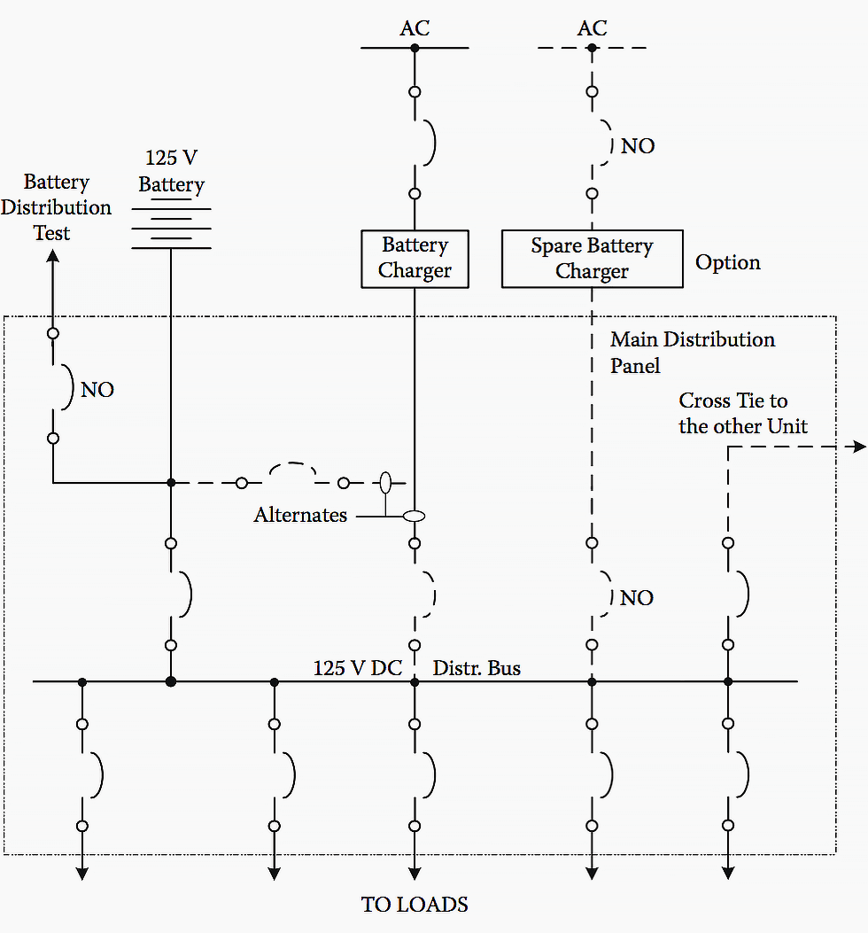
The method of connection of the battery, battery charger, and DC distribution systems depends on the duty, the type or load, and whether the system needs to be duplicated or whether duplicate chargers are required. One typical example for a 125 V system is shown in figure 1 below.

In this example, an alternative connection is shown for the battery-to-charger connection, and that alternative is preferred when sensitive digital systems are being fed or when there is a longer distance between the distribution panel and the batteries and charger.
This alternative has the advantage that the battery capacitance acts as a filter and reduces the electrical noise on the DC bus and limits interference into associated electronic and communication systems.


- All breakers normally closed except those marked “NO”
- “———–” indicates optional or alternative features
- Fuse may be substituted for circuit breakers for any or all circuits except where transfer switching is required
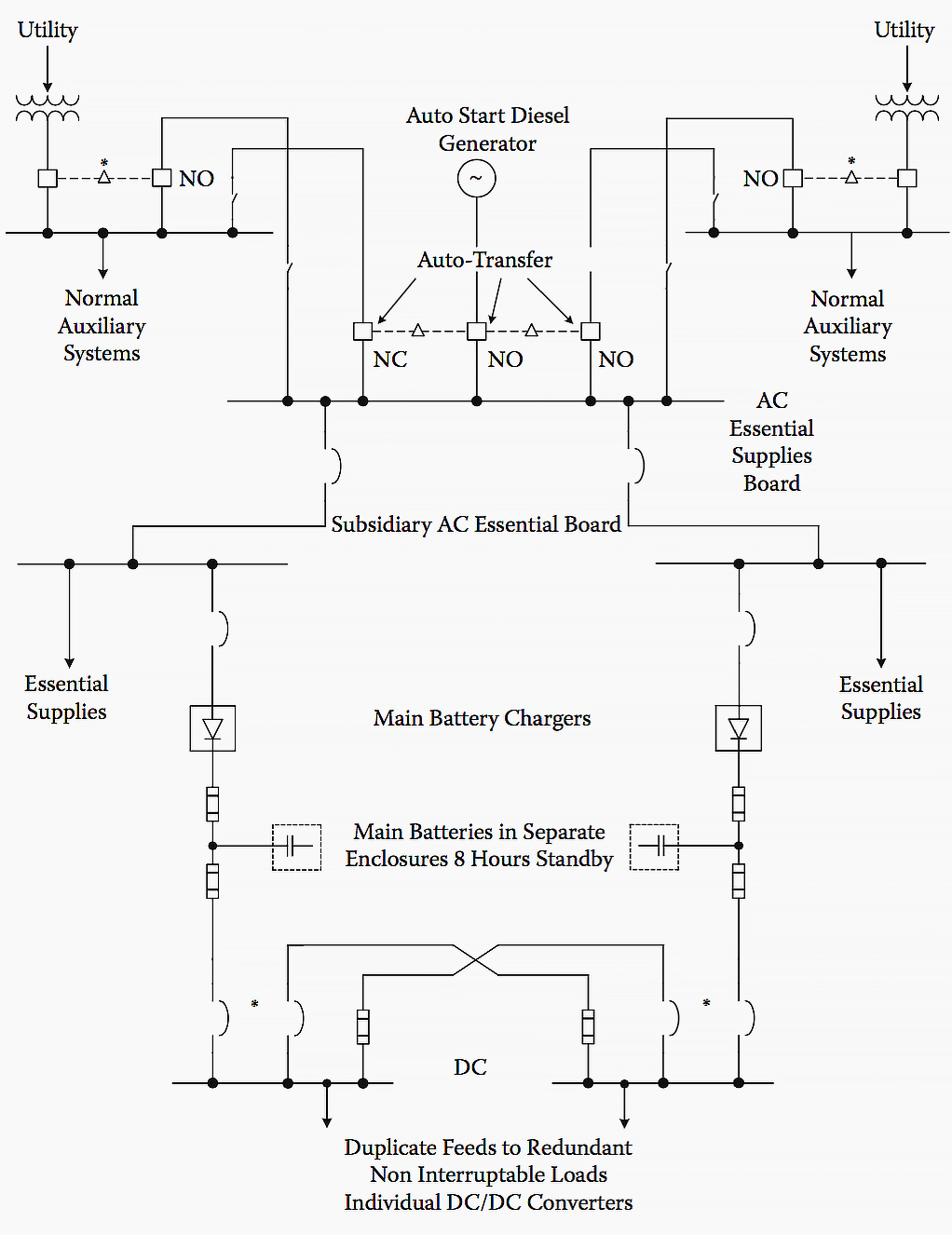
Figure 1 also shows the possibility of cross connection to a second DC system, and figure 2 shows a fully duplicated high-reliability system with manual transfer capabilities.
Similarly, in fig. 1, a standby battery charger is shown with its circuit breaker normally open. Again, by providing blocking diodes on each charger feed and purchasing chargers designed to operate in parallel, both chargers could be operated simultaneously to share the load. An extension to such a system, which would be applicable when high-reliability DC supplies are necessary, is shown in figure 2.
As in all dual, dual-supply, or redundant application cases, it is essential to minimize and, if possible, eliminate common-cause events that fail both systems. This aspect should always be considered when deciding whether to apply live or dead transfer and/or dually powered devices or deciding to provide totally independent redundant systems.


In the example shown in figure 2 above, the AC system feed and the DC transfer connnections use a crossover circuit rather than a single tie switch. Such a connection provides a simple transfer connection for operation and interlocking and allows each switch or circuit breaker in the transfer arrangements to be isolated for maintenance without the need to shut down both supply systems.
Battery protection fuses are shown. The application of such fuses is to protect both the battery and the battery cables to the maximum extent possible. In this particular example, fuses are provided on both the charger and feeder side to avoid the risk of a fuse operation disconnecting the battery while leaving the charger feeding the DC loads alone.
This connection is required if the charger regulation and filtering is such that the resultant feed is unsuitable to feed sensitive electronic systems.
In many cases, unless special-duty chargers are purchased, the charger can, if operated without a battery connection, cause premature power supply failure and unacceptable electrical noise levels in the distribution system.
For any battery-protection fuse arrangement, the fuses should be located as close as possible to the battery.
However, for those batteries and battery configurations that can cause accumulation of explosive by-products, such as free-breathing and vented lead-acid batteries in battery rooms, the fuses need to be placed in a suitable protected enclosure, mounted just outside the battery room.
In such cases, separate positive and negative connections should be run from the fuse enclosure to each battery terminal, thereby retaining the maximum possible separation. This needs to be done to minimize the risk of a fault between poles in the unprotected zone. However, from the fuses to the charger and the distribution boards, standard-two conductor cable could be used.


Dual battery system with single distribution
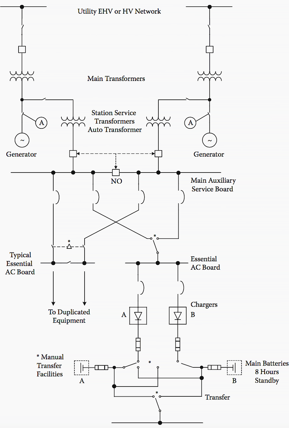
A third example is shown in figure 3, which is an example of a dual supply and dual battery AC and DC power supply arrangement. For a small hydroelectric generating station, AC and DC distribution supply is used. However, the transfer switch arrangements shown between the chargers and the two batteries in this example, which allow either charger to charge either battery, are less common.


In this arrangement, the battery protection fuse is a single fuse in the battery connection and would be suitable where the enhanced-performance chargers are used or if the downstream devices have wide power supply voltage range and have enhanced electrical noise withstand levels. Such battery fuse arrangements were also common when only electromechanical relay devices were used, noting that there were still risks in operation on a charger alone if emergency DC motors were fed from the same bus.
The single transfer switch arrangement to switch between the two battery systems would be typical for stations where operators were available to make the transfer if there were a failure on either battery system.
For remotely controlled stations or for sites where automated transfer is more appropriate, the single transfer switch could be replaced by an interlocked autotransfer arrangement.
This could also be provided with a short parallel (make before break) transfer by the addition of blocking diodes in each battery feed, noting that the provision of blocking diodes and protective circuit breakers would also make a continuous dual-feed arrangement feasible.
Reference // Industrial power systems by Shoaib Khan (purchase from Amazon)


What is the standard for 24VDC distribution system , What is the protection required and what is the rules then ?
Looks like there are harmonics in the AC supply from generator.
Due to other loads, sine wave output AC voltage of generator is getting distorted, which is causing harmonics in the AC voltage. This harmonic content is causing heating due to increased IRON LOSS in motors.
This is also clear from your statement that “when operated alone without other loads it works normally”. WITHOUT other loads, AC voltage waveshape of the generator is not getting distorted, so harmonics are not there & thus heating is not there.
Iam facing a problem in a factory supplied by parallel ac diesel generators – for some DC motor controllers there is noice and overheat without any normal reason – while when operated alone without other loads it works normally
dear
i want to design a transformer protection cubicle it just contain 4000A redrawable CB i ask for precautions to take in design and cable terminations to busbar (4 bars of 80x10mm)
thanks advance to direct me
best regards ” i think my english is clear my second language is french”
Why can’t we use 12v DC system for substations ?. Please reply me through this email address.
It’s very good portal and thanks
You’re welcome Jon, glad you like it.
In fig. 1 how do you ensure that battery charger output voltage does not damage the load under all charging condition?
Dear Edvard You ‘re wonderful.