
Estimated Study Time: 23 minutes
Introduction to DC sources
DC sources refer to sources of electrical energy which are associated with constant voltages and currents. A DC power supply can be constructed as an electronic circuit operating from the ac mains electricity supply and designed for purpose.
 Lecture Notes In DC Electric Sources and Principles Of Electrical Circuits
Alternatively it can be obtained from a battery, with the latter being used in portable equipment and machines where a connection to the mains ac supply is not convenient or practical.
DC circuits essentially contain only DC power sources and resistive elements and therefore form a suitable basis for studying the fundamental principles of electrical circuit analysis.
Let’s break this article into few sections and start the lecture notes:
1. Few Words About Batteries
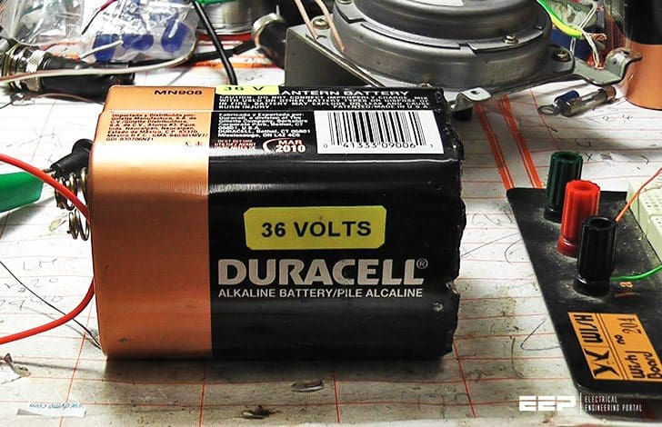
The DC battery is common place today. Batteries are used in the widest range of scenarios, from the smallest applications in hearing aids and small digital watches to the large heavy-duty lead acid batteries used in the automotive industry.
The voltage cell was invented by Alessandro Volta (1745-1827), an Italian physicist in 1792 during his work on electrolysis and the first battery as a stack of such cells in 1800.

Today, the term cell and battery are used almost interchangeably, but many low-voltage batteries are in fact single voltaic cells while strictly-speaking a battery is a number of cells stacked in series to obtain higher voltages than a single cell can provide.
There are basically two classes of battery, disposable and rechargeable.
1.1. Disposable Battery
The disposable battery, as the name suggests, is intended for a single use only, so that once the energy contained within the chemical constituents of battery is converted into electrical form then the battery is ‘used up’ and is disposed of.
These batteries are sometimes referred to as primary cells and include the common Zinc-Carbon (ZnC) AAA, AA, C and D cells or their equivalent alkaline Manganese-Dioxide (MnO2) versions as well as the myriad of small button cells using Zinc-Oxide (ZnO), Silver-Oxide (AgO) or ChromiumDioxide (CrO2) among other materials.
1.2. Rechargeable Battery
The second class of battery is the well known rechargeable type, which has gained widely increased usage in the past two or three decades.
In this type of battery when the chemical energy stored has been used up it can be replaced by a reversal of the chemical process through the use of electricity to ‘recharge’ it which can be done from a mains supply.
Thus the charge stored by this type of battery can be replenished and the battery can be used in sequential charge and recharge cycles.
1.3. Battery Construction
The construction and use of a typical C or D type cell is illustrated in Figure 1. The outer metal case in the form of a cylindrical container is made of Zinc and acts as the negative electrode of the cell. Its base also serves as the negative terminal of the battery.
The cylinder is filled with a chemical compound which acts as an electrolyte.
In modern batteries this is in non-liquid form of a paste or dry compound.
The positive electrode of the cell takes the form of a Carbon or Graphite rod with a metal cap which is inserted into the electrolyte in the centre of the cylinder. The metal cap on the rod serves as the positive terminal of the battery.

When a conducting resistive load is connected between the positive and negative terminals of the battery a closed electrical circuit is formed. Under this condition a number of chemical reactions take place in the electrolyte which results in the generation of positively charged ions and free negatively charged electrons within it.
The positive ions migrate through the electrolyte towards the carbon rod and become deposited on it. The electrons, on the other hand, cannot migrate through the electrolyte because its chemical composition forms a barrier which inhibits the passage of electrons through it.
Instead, the electrons accumulate at the negative electrode of the cell. This gives rise to a potential difference between the two terminals of the battery, which results in an emf or electric field across the resistive load connected between them. The emf then causes the electrons to flow in the external electric circuit through the load and finally to the positive terminal of the battery.
This gives rise to a continuous flow of current in the electric circuit.
In the circuit shown in Figure 1 the electrical load is the light bulb and the energy drawn from the battery by the bulb is emitted as visible light. As long as the closed electric circuit exists the current continues to flow and the electrochemical process in the electrolyte continues with the constituent chemicals being converted into other chemicals.
Eventually the supply of original chemicals in the electrolyte becomes depleted and the emf generated between the terminals of the battery drops, ultimately to zero, and the battery becomes discharged.
At this stage a disposable battery is discarded, while a rechargeable battery will be placed on a charger which reverses the electrochemical process in the electrolyte and restores charge to the battery by passing an electric current through it in the reverse direction for a sufficient period of time.
The length of time for which a battery lasts is determined by the amount of charge it stores in total and the rate at which this charge is used, which in turn depends on the magnitude of the current drawn from it.
A battery will last longer when a low value of current is drawn from it than it will when a high value of current is demanded.
This is indicated in Figure 2, where the terminal voltage of a battery is plotted against time for different values of current drawn from it with I4 > I3 > I2 > I1.

The operating lifetime (disposable) or cycle time (rechargeable) depends essentially on the amount of charge it stores in the electrolyte, which can be converted into free electrons to provide the current in an electric circuit.
One might then expect this battery capacity to be expressed as a quantity of charge in Coulombs.
This allows the effective lifetime of the battery to be calculated for different levels of current drawn from it as indicated in Table 1.
Table 1 – Battery Lifetime vs Current Drawn
| Battery Capacity | Current Drawn | Lifetime |
| 10 Ahr | 10 A | 1 hr |
| 10 Ahr | 1 A | 10 hr |
| 10 Ahr | 20 A | 30 mins |
| 10 Ahr | 0.25 A | 40 hrs |
| 1 Ahr | 1 A | 1 hr |
| 1 Ahr | 5 A | 12 mins |
| 1 Ahr | 100 mA | 10 hr |
It is also important, however, to realise that in practice there is a maximum current which a battery is able to deliver and this must also be taken into account when choosing a suitable battery for a particular application.
For example, the 1 Ahr battery of Table 1 may not be able to deliver a current as high as 5A due to the limitations of its chemistry and in this case could not be used in a scenario where this level of current is demanded, even for the short period of 12 mins.
2. The Ideal Voltage Source
The symbol already used for a DC battery is used for an ideal DC voltage source as shown in Figure 3. The emf of an ideal battery is the sum of the cell voltages which are stacked to obtain a higher voltage than a single cell can provide.
An ideal voltage source is one which provides a constant output voltage regardless of the load placed on it.
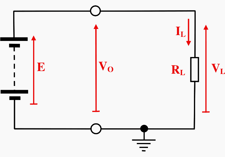
The definitive characteristic of the ideal voltage source is therefore:
VO = E
That is, the output or terminal voltage of the battery as measured between its positive and negative terminals is always the internal collective cell voltage, E.
Since the output voltage of the battery, VO, is in this case identical to the voltage across the single load resistor VL, then from Ohm’s law we have:
IL = VL / RL = E / RL
This shows that the current through the load is a function of the resistance, RL, with the voltage across the load being independent of it.
Clearly, a situation like this cannot prevail in reality.
For example, if a piece of heavy-duty conducting cable were placed across a 12V lead-acid car battery, the battery would rapidly overheat, vent Hydrogen gas, melt and possibly explode. Therefore, the concept of a short-circuit load is primarily a theoretical one to be used only on paper for the purposes of circuit analysis.
However, there are scenarios in practice where electronic equipment must be protected against damage in the event of a short-circuit occurring unintentionally or inadvertently.
3. The Ideal Current Source
It is sometimes necessary to generate a defined and constant value of current to drive a circuit or load rather than a constant voltage. This is known as a current source, the most common symbol for which used is the double overlapping circles shown in Figure 4.
Note that the direction of the current generated to flow out of the terminals of the source must be indicated in some manner, usually by a directed arrow.
Current sources do not occur naturally in cell form like batteries and are constructed using electronic circuits which are in turn powered from a voltage source.
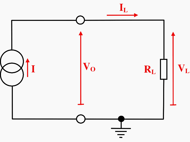
The definitive characteristic of the ideal current source is that:
IL = I
That is, the current which flows out of the positive terminal of the current source, around the circuit through the load resistor, RL, and back into the negative terminal of the source is always equal to the nominal value of the current source, I.
This value is independent of the value of the load resistance, RL. The voltage developed across the load, VL, is given by Ohm’s law as:
VL = ILRL = IRL
This shows that the voltage across the load, which is also the voltage which is developed across the current source itself, is a function of the resistance, RL.
The voltage developed across the terminal of the current source will adjust itself to be equal to the battery voltage.

4. The Non-Ideal Voltage Source
In practice a voltage source is not ideal and does not provide unlimited current. When the battery or voltage source is not connected to a load, the voltage between its terminals is referred to as its open-circuit terminal voltage, VOC, and is essentially the same as the cell voltage, E.
However, when a load is connected to the source, the terminal voltage drops as current is drawn from it so that:
VO < E or VO < VOC
This effect can be observed in the curves shown in Figure 2 where the voltage available from the battery is slightly lower than the open circuit voltage, VOC, and the drop in voltage becomes more pronounced as the current drawn from the battery is increased.
This can then be represented as an ideal voltage source generating the cell voltage, E, with an internal source resistance, RS connected in series with the ideal source and its output terminals as shown in Figure 6.
In this case the current drawn from the supply flows through the internal source resistance, RS, giving rise to a potential drop across it, VS.
In this case by Kirchhoff’s Law:
VO = E − VS
But from Ohm’s Law:
VS = ILRS
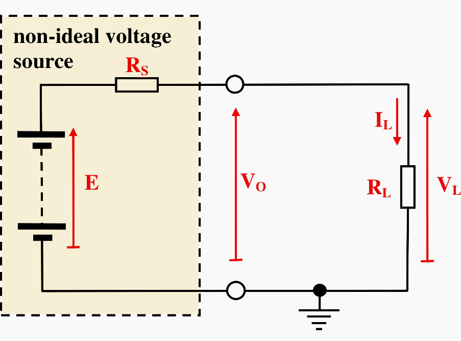
so that:
VO = E − ILRS
Note also that for the load:
VL = ILRL
From the relation for resistors connected in series we have:
IL = E / (RL + RS)
So that finally:
VL = RL E / (RL + RS)
This has the effect of reducing the effective output voltage of the battery.
5. The Non-Ideal Current Source
In a similar manner in practice, a current source is not ideal. The output current provided by a non-ideal current source varies slightly with a change in the load resistance connected to it. This effect can be modelled by attributing an internal resistance to the current source in a similar manner to the non-ideal voltage source.
However, the internal resistance is connected across the ideal current source in this case rather than in series with it as shown in Figure 7.
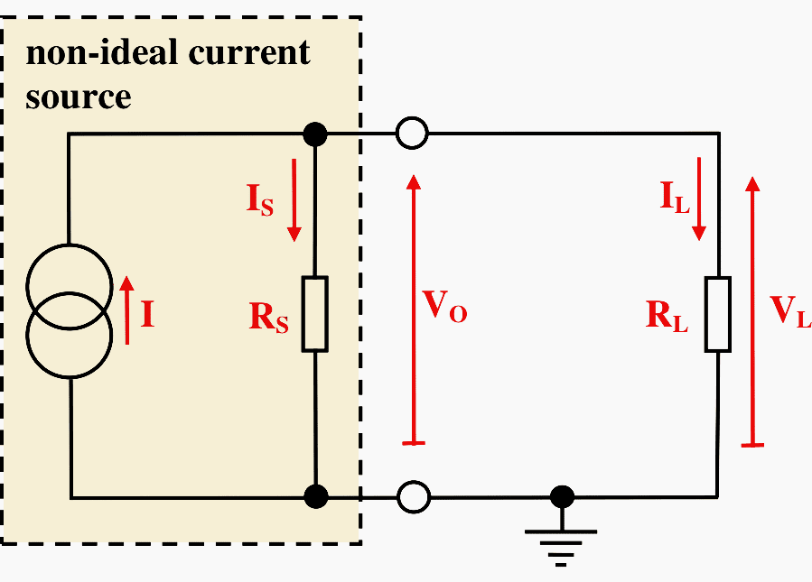
In the case of the non-ideal current source the internal resistance, RS, is much higher than that in the case of the non-ideal voltage source.
The effect of the internal resistance in the non-ideal current source is to shunt some of the current generated by the ideal current source, I, so that the current which flows through the load, IL, is less than the ideal value.
In this case:
IL < I
The degree of drop in the output current from the ideal value depends on the value of the load resistance, RL, by comparison with the internal source resistance, RS.
If Kirchhoff’s Current Law is applied to the positive output terminal of the current source we have:
I = IS + IL
From previous work on current splitting between resistors in parallel:
IL = RSI / (RS + RL)
Note also that for the load:
VL = ILRL
so that:
VL = RSRLI / (RS + RL)
6. Energy Expenditure and Power Dissipation
In the circuits above the load resistance, RL, represents the electrical equivalent of some form of load which demands or uses energy.
For example, when the bulb in a torch powered by batteries lights up, electrical energy is drawn from the batteries and converted into light. This uses up the energy stored in the batteries and the rate at which the energy is depleted depends on the brightness of the bulb, often referred as its wattage.
If it is recalled that power dissipated is the rate at which energy is expended per unit time, then:

The unit of Energy is the Joule (J), called after the English physicist James Prescott Joule (1818-89), who discovered the first law of thermodynamics. The unit of power is the Watt (W), named after James Watt (1736-1819), a Scottish mechanical engineer and developer of the steam engine.
Then for a resistive element in an electric circuit with a potential drop, V across it and a current, I flowing through it we have:
P = VI
But from Ohm’s Law we recall:
V = IR or I = V / R
so that:
P = VI = I2 R = V2 / R
Reference // DC Circuit Analysis – Lecture 5: DC Electric Sources, Energy and Power
Related electrical guides & articles


Edvard Csanyi
Hi, I'm an electrical engineer, programmer and founder of EEP - Electrical Engineering Portal. I worked twelve years at Schneider Electric in the position of technical support for low- and medium-voltage projects and the design of busbar trunking systems.I'm highly specialized in the design of LV/MV switchgear and low-voltage, high-power busbar trunking (<6300A) in substations, commercial buildings and industry facilities. I'm also a professional in AutoCAD programming.
Profile: Edvard Csanyi

Inverter and UPS both uses batteries sand give ac output, then why we say UPS and somewhere Inverter?
Excellent article
After long time, good article was published on DC Sources of BATTERYS by EDWARD.. Lot of thanks for your effort.
The work you are doing in the field of electrical engineering is very useful and rich of information for various categories of people interested in electrical theories and practices. I appreciate a lot the effor
of all those making it possible benefit
I feel so appreciated with the articles news lectures ….etc you made
i am following all articles hope more prosperious