
Estimated Study Time: 9 minutes
DC Testing Methods
Let’s take a look at the two important tests that are conducted with DC voltage. Two tests can be conducted on solid insulation using following DC testing methods: insulation resistance testing and high-potential (Hi-pot) voltage testing.
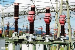
 DC Testing Methods Conducted On Solid Insulation (photo credit: HAEFELY HIPOTRONICS via Youtube)
Table of contents:
1. Insulation Resistance Testing
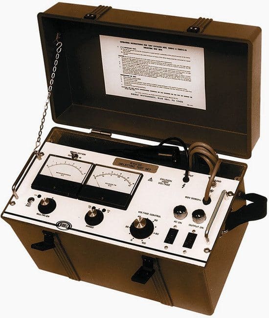
This test may be conducted at applied voltages of 100–15,000 V. The instrument used is a megohmmeter, either hand cranked, motor driven, or electronic, which indicates the insulation resistance in megohms. An electronic megohmmeter is shown in Figure 1 below.
The quality of insulation is a variable, dependent upon temperature, humidity, and other environmental factors.

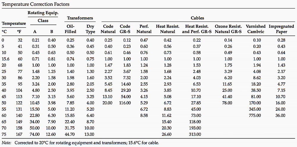
Therefore, all readings must be corrected to the standard temperature for the class of equipment under test. The temperature correction factors for various electrical apparatus are shown in Table 1 below (click to enlarge table).
This test can be useful in giving an indication of deteriorating trends in the insulation system. The insulation resistance values by themselves neither indicate the weakness of the insulation nor its total dielectric strength.
However, they can indicate the contamination of the insulation and trouble ahead within the insulation system if a downward trend continued in the insulation resistance values.
Insulation resistance measurement values can be accomplished by 4 common test methods:
- Short-time readings
- Time-resistance readings (dielectric absorption ratio [DAR] test)
- Polarization index (PI) test
- Step-voltage readings
1.1 Short-Time Readings
This test simply measures the insulation resistance value for a short duration of time, such as 30 or 60 s, through a spot reading that lies on the curve of increasing insulation resistance values. The reading only allows a rough check of the insulation condition.
However, comparison of this value with previous values is of importance. A continued downward trend is indicative of insulation deterioration ahead.
For interpreting the results, the values used for comparison should all be normalized to 20°C with humidity effects considered.
1.2 Time–Resistance Readings
A good insulation system shows a continued increase in its resistance value over the period of time in which voltage is applied. On the other hand, an insulation system that is contaminated with moisture, dirt, and the like will show a low resistance value.
The time-resistance method is independent of temperature and equipment size. It can provide conclusive results as to the condition of the insulation. The ratio of time-resistance readings can be used to indicate the condition of the insulation system. The ratio of a 60s reading to a 30s reading is called the DAR //
DAR = Resistance reading at 60s / Resistance reading at 30s
A DAR ratio below 1.25 is cause for investigation and possible repair of the electrical apparatus. Usually, the DAR readings are confined to the hand-driven megohmmeter.
1.3 PI Test
The PI test is a specialized application of the dielectric absorption test. The PI is the ratio of the insulation resistance at 10 min to the insulation resistance at 1 min. A PI of less than 1 indicates equipment deterioration and the need for immediate maintenance.
This test is used for dry insulation systems such as dry type transformers, cables, rotating machines, etc.
1.4 Step-Voltage Readings (DC Voltage Tip-Up Test)
In this method, voltage is applied in steps to the insulation under test by a way of a controlled voltage method. As voltage is increased, the weak insulation will show lower resistance that was not obvious at lower voltage levels.
Moisture, dirt, and other contaminants can be detected at lower voltage levels, that is, below operating voltages, whereas aging and physical damage in clean, dry insulation systems can only be revealed at higher voltages.
The step-voltage test is very valuable when conducted on a regular periodic basis.
DC Testing Methods ↑ | Measurement Values ↑
2. High-Potential Voltage Test
A DC hi-pot voltage test is a voltage applied across the insulation at or above the DC equivalent of the 60 Hz operating crest voltage (i.e., DC value=1.41 times RMS value). This test can be applied as a step-voltage test. When the high-potential voltage is applied as a dielectric absorption test, the maximum voltage is applied gradually over a period of 60–90 s.
When this test is applied as a step-voltage test, the maximum voltage is applied in a number of equal increments, usually not less than eight, with each voltage step being held for an equal interval of time. The time interval between each step should be 1–4 min. At the end of each interval, a leakage current or insulation resistance reading is taken before proceeding to the next step.
A plot of test voltage versus leakage current or insulation resistance can then be drawn to indicate the condition of the insulation system. Routine maintenance tests are conducted with a maximum voltage at or below 75% of the maximum test voltage permitted for acceptance tests, or at 60% of the factory test voltage.
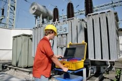
A 15 kV DC dielectric test set is shown in Figure 2 below //
Dielectric absorption test
The dielectric absorption test is conducted at voltages much higher than the usual insulation resistance test values and can exceed 100kV.
The test is evaluated on the basis of insulation resistance. If insulation is in good condition, the apparent insulation resistance will increase as the test progresses. The dielectric absorption tests are independent of the volume and the temperature of the insulation under test.
Reference // Electrical Power Equipment Maintenance and Testing by Paul Gill
Related electrical guides & articles


Edvard Csanyi
Hi, I'm an electrical engineer, programmer and founder of EEP - Electrical Engineering Portal. I worked twelve years at Schneider Electric in the position of technical support for low- and medium-voltage projects and the design of busbar trunking systems.I'm highly specialized in the design of LV/MV switchgear and low-voltage, high-power busbar trunking (<6300A) in substations, commercial buildings and industry facilities. I'm also a professional in AutoCAD programming.
Profile: Edvard Csanyi

Very interesting topic. I’m trying to learn more about temperature correction for insulation resistance. Can you tell me from where is this table.
I love the topic and I’ve a lot about DC testing especially the tip up test. Thanks a lot.
You’re welcome, Raul.