
Estimated Study Time: 12 minutes
Content
- Type of Capacitor Bank as per Its Application:
- Type of Capacitor as per Construction
- Selecting Size of Capacitor Bank
- Selection of Capacitor as per Non Liner Load
- Configuration of Capacitor:
- Effect of series and Parallel Connection of capacitor:
Type of Capacitor Bank as per Its Application
1. Fixed type capacitor banks
The reactive power supplied by the fixed capacitor bank is constant irrespective of any variations in the power factor and the load of the receivers. These capacitor banks are switched on either manually (circuit breaker / switch) or semi automatically by a remote-controlled contactor.
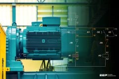
 Defining size and location of capacitor in electrical system
These capacitors are applied at the terminals of inductive loads (mainly motors), at bus bars.
Disadvantages:
- Manual ON/OFF operation.
- Not meet the require kvar under varying loads.
- Penalty by electricity authority.
- Power factor also varies as a function of the load requirements so it is difficult to maintain a consistent power factor by use of Fixed Compensation i.e. fixed capacitors.
- Fixed Capacitor may provide leading power factor under light load conditions, Due to this result in overvoltages, saturation of transformers, mal-operation of diesel generating sets, penalties by electric supply authorities.
Application:
- Where the load factor is reasonably constant.
- Electrical installations with constant load operating 24 hours a day
- Reactive compensation of transformers.
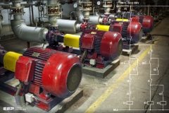
- Individual compensation of motors.
- Where the kvar rating of the capacitors is less than, or equal to 15% of the supply transformer rating, a fixed value of compensation is appropriate.
- Size of Fixed Capacitor bank Qc ≤ 15% kVA transformer
2. Automatic type capacitor banks
The reactive power supplied by the capacitor bank can be adjusted according to variations in the power factor and the load of the receivers.
The equipment is applied at points in an installation where the active-power or reactive power variations are relatively large, for example:
- At the bus bars of a main distribution switch-board,
- At the terminals of a heavily-loaded feeder cable.
Where the kvar rating of the capacitors is less than, or equal to 15% of the supply transformer rating, a fixed value of compensation is appropriate.
Above the 15% level, it is advisable to install an automatically-controlled bank of capacitors.
Control is usually provided by contactors. For compensation of highly fluctuating loads, fast and highly repetitive connection of capacitors is necessary, and static switches must be used.
Types of APFC – Automatic Power Factor Correction
Automatic Power Factor correction equipment is divided into three major categories:
- Standard = Capacitor + Fuse + Contactor + Controller
- De tuned = Capacitor + De tuning Reactor + Fuse + Contactor + Controller
- Filtered = Capacitor + Filter Reactor + Fuse + Contactor + Controller.
Advantages:
- Consistently high power factor under fluctuating loads.
- Prevention of leading power factor.
- Eliminate power factor penalty.
- Lower energy consumption by reducing losses.
- Continuously sense and monitor load.
- Automatically switch on/off relevant capacitors steps for consistent power factor.
- Ensures easy user interface.
- Automatically variation, without manual intervention, the compensation to suit the load requirements.
Application:
- Variable load electrical installations.
- Compensation of main LV distribution boards or major outgoing lines.
- Above the 15% level, it is advisable to install an automatically-controlled bank of capacitors.
- Size of Automatic Capacitor bank Qc > 15% kVA transformer.
| Method | Advantages | Disadvantages |
| Individual capacitors | Most technically efficient, most flexible | Higher installation & maintenance cost |
| Fixed bank | Most economical, fewer installations | Less flexible, requires switches and/or circuit breakers |
| Automatic bank | Best for variable loads, prevents over voltages, low installation cost | Higher equipment cost |
| Combination | Most practical for larger numbers of motors | Least flexible |
Type of Capacitor as per Construction
1. Standard duty Capacitor
Construction: Rectangular and Cylindrical (Resin filled / Resin coated-Dry)
Application:
- Steady inductive load.
- Non linear up to 10%.
- For Agriculture duty.
2. Heavy-duty
Construction: Rectangular and Cylindrical (Resin filled / Resin coated-Dry/oil/gas)
Application:
- Suitable for fluctuating load.
- Non linear up to 20%.
- Suitable for APFC Panel.
- Harmonic filtering
3. LT Capacitor
Application:
- Suitable for fluctuating load.
- Non linear up to 20%.
- Suitable for APFC Panel & Harmonic filter application.
Selecting Size of Capacitor Bank
The size of the inductive load is large enough to select the minimum size of capacitors that is practical.
For HT capacitors the minimum ratings that are practical are as follows:
| System Voltage | Minimum rating of capacitor bank |
| 3.3 KV , 6.6KV | 75 Kvar |
| 11 KV | 200 Kvar |
| 22 KV | 400 Kvar |
| 33 KV | 600 Kvar |
Unit sizes lower than above is not practical and economical to manufacture.
When capacitors are connected directly across motors it must be ensured that the rated current of the capacitor bank should not exceed 90% of the no-load current of the motor to avoid self-excitation of the motor and also over compensation.
Crane motors or like, where the motors can be rotated by mechanical load and motors with electrical braking systems, should never be compensated by capacitors directly across motor terminals.
For direct compensation across transformers the capacitor rating should not exceed 90 % of the no-load KVA of the motor.
Selection of Capacitor as per Non Liner Load
For power Factor correction it is need to first decide which type of capacitor is used.
Selection of Capacitor is depending upon many factor i.e. operating life, Number of Operation, Peak Inrush current withstand capacity.
- Calculation of Non liner Load, Example: Transformer Rating 1MVA,Non Liner Load 100KVA
- % of non Liner Load = (Non Liner Load/Transformer Capacity) x100 = (100/1000) x100=10%.
- According to Non Linear Load Select Capacitor as per Following Table.
| % Non Liner Load | Type of Capacitor |
| <=10% | Standard Duty |
| Up to 15% | Heavy Duty |
| Up to 20% | Super Heavy Duty |
| Up to 25% | Capacitor +Reactor (Detuned) |
| Above 30% |
Configuration of Capacitor
Power factor correction capacitor banks can be configured in the following ways:
- Delta connected Bank.
- Star-Solidly Grounded Bank.
- Star-Ungrounded Bank.
1. Star-Solidly Grounded
- Initial cost of the bank may be lower since the neutral does not have to be insulated from ground.
- Capacitor switch recovery voltages are reduced
- High inrush currents may occur in the station ground system.
- The grounded-Star arrangement provides a low-impedance fault path which may require revision to the existing system ground protection scheme.
- Typically not applied to ungrounded systems. When applied to resistance-grounded systems, difficulty in coordination between capacitor fuses and upstream ground protection relays (consider coordination of 40 A fuses with a 400 A grounded system).
- Application: Typical for smaller installations (since auxiliary equipment is not required)
2. Star-Ungrounded
Industrial and commercial capacitor banks are normally connected ungrounded Star, with paralleled units to make up the total kvar.
If only one unit is needed to make the total kvar, the units in the other phases will not be overloaded if it fails.
In industrial or commercial power systems the capacitors are not grounded for a variety of reasons. Industrial systems are often resistance grounded. A grounded Star connection on the capacitor bank would provide a path for zero sequence currents and the possibility of a false operation of ground fault relays.
Also, the protective relay scheme would be sensitive to system line-to-ground voltage Unbalance, which could also result in false relay tripping.
Application: In Industrial and Commercial.
3. Delta-connected Banks
Delta-connected banks are generally used only at distributions voltages and are configured with a Single series group of capacitors rated at line-to-line voltage. With only one series group of units no overvoltage occurs across the remaining capacitor units from the isolation of a faulted capacitor unit.
Therefore, unbalance detection is not required for protection and they are not treated further in this paper.
Application: In Distribution System.
Effect of series and Parallel Connection of capacitor
Parallel Connection
This is the most popular method of connection. The capacitor is connected in parallel to the unit. The voltage rating of the capacitor is usually the same as or a little higher than the system voltage.
Series Connection
This method of connection is not much common. Even though the voltage regulation is much high in this method,
It has many disadvantages.
One is that because of the series connection, in a short circuit condition the capacitor should be able to withstand the high current. The other is that due to the series connection due to the inductivity of the line there can be a resonance occurring at a certain capacitive value.
This will lead to very low impedance and may cause very high currents to flow through the lines.
Related electrical guides & articles


Jignesh Parmar
Electrical Middle management professional having more than 22 years rich and dynamic experience in Project Execution / Project Management / Designing / Maintenance diversifies from Electrical Power Transmission (400KV/220KV/66KV)- Distribution(11KV/220V) to Lifts-HVAC-Ventilation-Fire Fighting-Fire Alarm-Lifts-CCTV-Stack Parking Works (High Rise Buildings, Townships, Shopping Complex, Commercial Complex, School, Temple).Profile: Jignesh Parmar

We have 400KVA 11KV / 0.433KV Dry Transformer. This Transformer is feeding power to MCC. We have APFC Panel connected with MCC . To compensate NO-Load Loss of Transformer ( Copper Loss) we have to provide Fixed Capacitor at LT side of Transformer. How to select rating of Capacitor ?
What’s the effect of short circuit current on busbar size of capacitor bank?
Dose the short circuit current affect the busbar size of capacitor bank?
Contents are very useful as practical problems faced are shared. Platf
Electrical details
sir,
Why the APFC Panel is not used with the HT panel ?
Apfc is available upyog 33kv in capacitor panel for reactive power compensation. See Crompton Greece’s panel.
Apfc is available upyog 33kv in capacitor panel for reactive power compensation. See Crompton Greece’s panel.
Where the APFC Panels cable should be connected: in a outgoing switch or in outgoing bus bar of ACB of a transformer ?
Pls suggest.
Dear Sir,
I have so many motor ( Total – 200 KVAR) with fixed capacitor with motor side, Now I want to add APFC panel in incomer ( 100 KVAR), Since total requirement is 300 KVAR.
Can we use APFC panel with fixed type capacitor.??
Dear Sir, Please tell us the HT Capacitor testing method before connection on 11KV Line.
We have HT Capacitor 11KV, 1 PH. ABB MAKE
What should be the capacitor switching current for the vacuum contactor in case of 11 KV 200 KVAR capacitor bank and its calculation
Crane motors or like, where the motors can be rotated by mechanical load and motors with electrical braking systems, should never be compensated by capacitors directly across motor terminals.
May I know why is it so?
How to calculate the size of Fixed capacitor Bank with respect to Transformer. Irrespective of load Transformer consumes some power, Though our load is switched OFF. so we need to place an fixed capacitor bank enen though we use Automatic capacitor banks for power factor correction. So we need to place one fixed capacitor bank in APFC Pannel how to calculate that fixed capcitor bank.
What is the percentage KVAR compensation required with respect to transformer size. What i know is about 6 to 8% of transformer KVA?? Please share your ideas and if you have any refrence standard please tell also
Thanks
You have Published Very Knowledgefull information.Thank for this valueable information
Dear sir ,
how much kvar capcitor used in 1250 Kva tranformer (33 kva supply system) for improve this power factor . Now its pf is 0.17
i have a three phase meter of 11 kva and two motor of 10KW and 5 KW respectively used simultaneously. My bill used to show the power factor between 0.80-0.85. After i installed the Sand Capacitor of 10 KVA the power decreased to 0.63 instead of increasing. Please help me
Great and very valuable information. Keep up the great work!
Dear sir
I have 400 kva transforme 11kv/400 volt and i am working on connecting a 250 kvar capacitor bank with five stage each one of 50 kvar so i connented two 25kvar together as one stage my question is can i connect 25 kvar capacitor to fuse first then connected to contactor thank you
I am working on to improve pf of my company. I am using a 3 phase power factor meter which reads individual phase pf and then average.
Could you pl. explain the meaning and significance of average power factor?
En BT si el factor de potencia es superior a 0,7 la regla general es poner un capacitor del 5% de la potencia aparente del transformador directo y un 25% de la potencia aparente del transformador con un banco con relé, a los motores que tienen una potencia elevada en relación al transformador se lo coloca un condensador fijo de un 30 % de su potencia en KW. En Chile tenemos red trifásica de 400 VAC y sistema de tierra TT. Como se indico si hay consumos permanentes en el tiempo sobre 150 KVA se coloca un banco de condensadores de media tensión fijo. Para armónicos se toman la suma de las cargas alinéales en relación con la potencia aparente del transformador, hasta un 20 % utilizar condensadores normales, entre un 20 y 50% se agregan la reactancias de línea de un 7% de la potencia del condensador ( sintoniza a 189 Hz.), sobre 50 %, de cargas alinéales utilizar transformador solo para estas cargas y filtro sintonizado (factor K consultar a proveedor del transformador). Los condensadores modernos soportan 440 VAC en forma permanente por cual aceptan las reactancias de línea que suben su tensión a 430 VAC. Esta información esta en catálogos de las marcas mas importantes de condensadores. Yo trabajo con marcas de Alemania, Japón, Corea y China. Relés de España, Italia y Taiwán, contactores e interruptores de Japón y no he tenido fallas atribuibles a los equipos los cuales cumplen las normas correspondientes. Agradezco al autor el excelente documento cuya información respalda mi experiencia.
hello sir
thank you for shearing you practical knowledge. Please explore the area of calculation of FACTS devices for p.f. improvement. This will help all new generation student.
may i have some guideline of de tuned reactor for 6.6kv capacitor bank?what are the calculation for selection of de tuned reactor?what are the limits as per standard guideline?
thanking u….
Hi,
How to calculate the size of Fixed capacitor Bank with respect to Transformer. Irrespective of load Transformer consumes some power, Though our load is switched OFF. so we need to place an fixed capacitor bank enen though we use Automatic capacitor banks for power factor correction. So we need to place one fixed capacitor bank in APFC Pannel how to calculate that fixed capcitor bank.
Thanking You,
Ravi