
Introduction to BIL – Basic Insulation Level
Insulation levels are designed to withstand surge voltages, rather than only normal operating voltages. Since the transmission & distribution lines and substation equipment are protected by surge arresters draining the surges rapidly before the insulation is damaged, the arrester must operate below the minimum insulation level that must withstand the surges.

An example is shown in Figure 1 below. The minimum level is known as the Basic Insulation Level (BIL) that must be that of all of the components of a system.
Insulation values above this level for the lines and equipment in the system must be so coordinated that specific protective devices operate satisfactorily below that minimum level.
In the design of lines and equipment considering the minimum level of insulation required, it is necessary to define surge voltage in terms of its peak value and return to lower values in terms of time or duration. Although the peak voltage may be considerably higher than normal voltage, the stress in the insulation may exist for only a very short period of time.
Figure 1 – Insulation coordination

For purposes of design, the voltage surge is defined as one that peaks in 1.5 microseconds and falls to one-half that value in 40 microseconds (thousandths of a second).
It is referred to as a 1.5/40 wave, the steep rising portion is called the wave front and the receding portion the wave tail, Figure 2.
Figure 2 – Surge Voltage 1.5 by 4.0 Wave

Insulation levels recommended for a number of voltage classes are listed in Table 1. As the operating voltages become higher, the effect of a surge voltage becomes less; hence, the ratio of the Basic Insulation Level (BIL) to the voltage class decreases as the latter increases.
Table 1[/highlight2] – Typical Basic Insulation Levels
| Basic insulation level, kV (standard 1.5- × 40-μs wave) | ||
| Voltage class, kV | Distribution class | Power class (station, transmission lines) |
| 1.2 | 30 | 45 |
| 2.5 | 45 | 60 |
| 5.0 | 60 | 75 |
| 8.7 | 75 | 95 |
| 15 | 95 | 110 |
| 23 | 110 | 150 |
| 34.5 | 150 | 200 |
| 46 | 200 | 250 |
| 69 | 250 | 350 |
*For current industry recommended values, refer to the latest revision of the National Electric Safety Code.
Distribution class BIL is less than that for power class substation and transmission lines as well as consumers’ equipment, so that should a surge result in failure, it will be on the utility’s distribution system where interruptions to consumers are limited and the utility better equipped to handle such failures.
The insulating characteristics of the line and equipment must exceed the voltage level at which the protection arrester initiates sparking to ground, and there must be a sufficient voltage differential between the two.
The characteristics of the several type arresters are shown in the curves of Figure 3.
Figure 3 – (a) Sparkover Characteristics of Distribution Value Arresters; (b) Sparkover Characteristics of Expulsion Arresters

The impulse level of lines and equipment must be high enough for the arresters to provide protection but low enough to be economically practical. Surges, on occasion, may damage the insulation of the protective device; hence, insulation coordination should include that of the protective devices.
As there are a number of protective devices, mentioned earlier, each having characteristics of its own, the characteristics of all of these must be coordinated for proper operation and protection.
Before leaving the subject of insulation coordination, such coordination also applies within a piece of equipment itself. The insulation associated with the several parts of the equipment must not only withstand the normal operating voltage, but also the higher surge voltage that may find its way into the equipment.
The weakest insulation should be weaker by a sufficient margin than that of the principal equipment it is protecting. Such coordinated arrangement restricts damage not only to the main parts of the equipment, but less so to parts more easily accessible for repair or replacement.
The insulation of all parts of the equipment should exceed the basic insulation level (BIL).
Figure 4 – Simplistic diagram illustrating Basic insulation level (BIL) and Insulation coordination
 and Insulation coordination")
Switching and Non-Switching Substation Equipment
Other equipment that may be present in a distribution substation comprises switch disconnectors, earthing switches, instrument transformers (CTs, VTs), measuring devices, protective relays, and occasionally, reactors, capacitors, street lighting equipment, and storage batteries.
Disconnect Switches and Earth Switches
Switches can be of various sorts, but their primary characteristic is that none are intended to interrupt fault currents; the insulation or insulators connected with them must coordinate with the overall system and have a Basic Insulation Level (BIL) sufficient for withstanding voltage spikes. Typically, they comprise a conductive blade, hinged at one end, and a fixed contact at the opposite end, with both terminals connected to appropriate insulators that meet the standard insulator specifications for BIL coordination.
Nearly every significant line or equipment in power substation is equipped with a mechanism for complete isolation from other powered components, serving as a sensible measure to ensure safety by averting accidental energization. These basic devices, referred to as disconnects or disconnecting switches, are often positioned on either side of the equipment or line where maintenance is required. .
For added safety, they may be operated using an insulated stick that enables the operator to maintain distance from the switch. Locking devices are occasionally installed to prevent disconnects from being inadvertently opened or from being forcefully opened during instances of substantial fault currents.
Figure 5 – 400 KV Disconnector Close Operation
While not intended for closure to activate the connected line or equipment, they may be closed under specific situations, provided that they close firmly and swiftly with due caution. Disconnects can be either single-blade devices or several units functioning in unison.
Air break switches has properties comparable to disconnects; however, their stationary contacts are fitted with arc suppression mechanisms, allowing them to be opened while powered, but with a limitation on the current that may be safely interrupted. The equipment may be a basic arcing horn that stretches the arc that may develop until it becomes unsustainable.
Another variant features a flexible “whip” connected to the fixed contact, which maintains contact with the moving blade until a threshold is reached, at which time the whip swiftly snaps open, effectively extinguishing any potential arc.[/info_box]
Oil switches utilize a blade that remains open from its contact submerged in oil, effectively suppressing any potential arc formation. They provide a greater current breaking capability than air break switches and are especially appropriate for underground systems or environments where moisture or pollution render air switches unfeasible.
Nevertheless, they involve higher initial costs, operational expenses, and maintenance requirements.
Figure 6 – 110kV oil switch disconnectors
Instrument Transformers (CTs, PTs)
Instrument transformers are utilized in substations due to the impracticality of measuring current and voltage values with standard meters, as these values may exceed the instruments’ range and the insulating challenges render direct usage unfeasible.
Instrument transformers function similarly to distribution transformers, although have significantly enhanced accuracy in their transformation ratios. Current transformers (CT) and potential transformers (PT) are insulated for withstanding the voltage of their connected circuits and comply with the Basic Insulation Level (BIL) and insulation coordination of their respective systems.
The turn ratios of the current transformer typically lead to an increase in voltage in its secondary winding. The voltage is significantly reduced by the impedance of the instrument or device connected to the secondary terminals; if the secondary is left open with no connection, the generated voltage may reach hazardous levels, necessitating a short circuit device for the current transformer when it is opened.
Current transformers are equipped with polarity indicators to facilitate their correct connection when paralleled with other current transformers.
The good and bad practices in the commissioning of current transformers in a substation
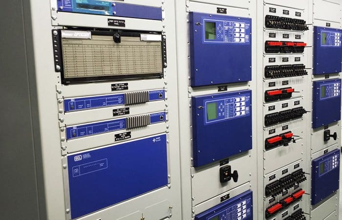
Protection Relays and Meters
The reader is presumed to possess knowledge of the functioning of meters that display and document data necessary for monitoring substation operations, encompassing both incoming and outgoing feeds.
Figure 7 – Metering control panels
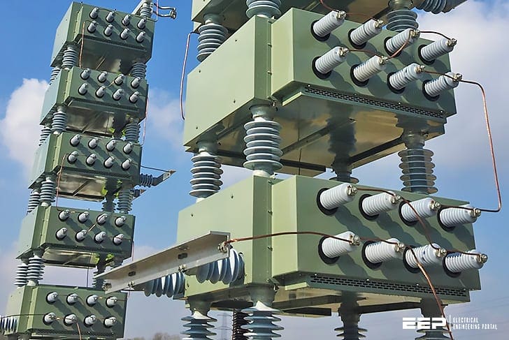
Capacitor Bank
Where needed, capacitors may be installed at distribution substations to regulate bus voltage through power factor correction. Provisions exist for activating and deactivating certain units inside the capacitor bank as necessary to sustain voltage regulation.
Capacitors are connected to the bus via fuses that isolate a faulty capacitor unit, hence preventing impact on other energized equipment inside the substation.
Figure 8 – High voltage capacitor banks
Reactors
Reactors can be arranged in series with the line or equipment to restrict the flow of fault current that may pass through them. They may also be connected in series with a transformer that can be paralleled with one of differing characteristics to achieve an equitable split of loads between them.
In distribution feeders, which are cables with metallic sheaths operating at elevated voltages, reactors may be implemented to mitigate the capacitance impact of the cables.
Lighting Systems
Street lighting systems providing series illumination may occasionally be located in distribution substations. Appendix E in this study contains the specifications of the equipment and the operational procedures.
Substation Batteries for Auxiliary supply
Storage batteries are typically located at certain distribution substations, particularly the larger and more significant ones. Circuit breakers, indication lamps, and other equipment are typically powered by alternating current from a dedicated transformer at the substation.
When the operation of these devices, particularly the reclosing of circuit breaker mechanisms, is critical, they are powered by a direct current source from a bank of storage batteries.
The batteries are perpetually charged by being linked to a 120-volt alternating current supply via rectifiers. Lead-acid batteries require ventilation due to the release of hydrogen and oxygen gasses, which form a potentially explosive mixture. Batteries are rated in ampere-hours.
AC Auxiliary Systems In Power Substations (Design Requirements and Equipment)
Fuses
Fuses offer protection by melting a fusible connection when the current above their rated capacity. They are available in many types and ratings for both voltage and current specifications. All fuses, from the relatively low voltage line fuses linked to distribution transformers to those on high voltage transmission lines, function on the same principle and possess distinct time-clearing characteristics that must be evaluated alongside the attributes of other protective devices within the system.
The insulation of their mountings must also adhere to the Basic Insulation Level (BIL) and synchronize with the system insulation.
Reference: Power Transmission and Distribution – Anthony J. Pansini
Related electrical guides & articles


Edvard Csanyi
Hi, I'm an electrical engineer, programmer and founder of EEP - Electrical Engineering Portal. I worked twelve years at Schneider Electric in the position of technical support for low- and medium-voltage projects and the design of busbar trunking systems.I'm highly specialized in the design of LV/MV switchgear and low-voltage, high-power busbar trunking (<6300A) in substations, commercial buildings and industry facilities. I'm also a professional in AutoCAD programming.
Profile: Edvard Csanyi

THANKS VERY INTERESING
Greetings
Please assist I have a 275kV line voltage and would like to know the BIL of it
Thanks in advance for your response it means a lot
Please suggest the clearance LT to HT winding and inter layer insulation of HT coil for resin casted potential transformer.
PT BIL is 95 kV,
we can’t achieve impulse test with 95 k, please help
It’s very good information for up coming young engg
We need more and more latest upcoming
Development update
What is the length of 110kV insulators considering BIL 650KV and Nominal creepage distance 3679mm? and how to calculate.
What is the correction factor in terms of insulation for a potential transformer rated at 15.5kV Insulation with 110kV BIL full wave. Being installed at the height of 3000meters.
nice Article.
Bil rating will vary from operating voltage level to level ?
Great article!
Good job Edvard. Your contribution to the industry is appreciated.
What is “BIL” Test ?
How to do “BIL” Test ?
BIL refer to lightning impulse test. can refer to IEC 60060-1
Waht Is BIL of below Rated Surge Arrester.
1)4.5kV
2)7.2kV
3)12kV
4)18kV
5)24kV
6)33kV
How its calculate Please explain.
Is insulation Levels presented in table 1 Phase-Neutral Voltage?
How would Basic Insulation Level vary as altitude where equipment is to be installed rises ?
good topic
There is a mistake below title Hot Swap Controllers PDF:
….one-half that value in 40 microseconds (thousandths of a second).
should be: millionth of a second.
Dear Sir/Madam,
can you tell me abt earth falut details…