VT Parameters
- Rated voltage factor
- Rated primary voltage (Up)
- Rated secondary voltage
- Accuracy power
- Accuracy class
- Voltage ratio error
- Phase or phase displacement error
- Rated thermal limiting output

Introduction to VTs
The voltage transformer must comply with the network specifications, this is essential.
As with any device, the voltage transformer must meet requirements relating to the voltage, current and frequency. Voltage transformer specifications are only valid for normal conditions of use. A derating should be provided for in accordance with the ambient temperature and the altitude.
The voltage factor is determined by the maximum operating voltage, which depends on the network earthing system and the way the VT’s primary winding is connected.
The voltage transformer must be able to withstand this maximum voltage for the time necessary to clear the fault (see Table 1 below).
Table 1 – Normal values of the rated voltage factor
| Rated voltage factor | Rated time | Primary winding connection method | Network earthing system |
| 1.2 | continuous | phase to phase | any |
| 1.2 | continuous | between the neutral point of a star transformer and earth | any |
| 1.2 | continuous | phase to earth | directly earthed neutral |
| 1.5 | 30 seconds | ||
| 1.2 | continuous | phase to earth | limiting resistance earthing with automatic earth fault clearance (tripping upon first fault) |
| 1.9 | 30 seconds | ||
| 1.2 | continuous | phase to earth | earthed neutral without automatic earth fault clearance (no tripping upon first fault) |
| 1.9 | 8 hours | ||
| 1.2 | continuous | phase to earth | tuned limiting reactance (or Petersen coil) earthing without automatic earth fault clearance (no tripping upon first fault) |
| 1.9 | 8 hours |
Note: smaller time ratings are permissible by agreement between manufacturer and user.
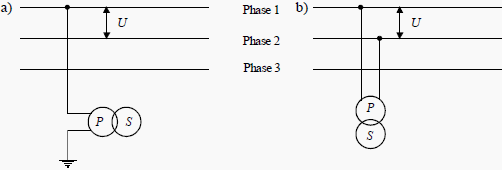
Rated primary voltage (Up): Depending on their design, voltage transformers will be connected either:
- Between phase and earth (see Figure 1a); or
- Between phases (see Figure 1b).


The voltage transformer must be suited to requirements relating to protection and measuring devices.
The foreseen application of the voltage transformer is used to determine the rated secondary voltage, the accuracy power, the accuracy class and the thermal power limit.
For example:
![]()
Accuracy power: this is expressed in VA and it is the apparent power that the voltage transformer can supply to the secondary when it is connected under its rated primary voltage and connected to its accuracyload. It must not introduce an error in excess of the values guaranteed by the accuracy class. Go to Top ↑
The standardized values are: 10 – 15 – 25 – 30 – 50 – 75 – 100 – 150 – 200 – 300 – 400 – 500 – VA.
Accuracy class: this defines the guaranteed transformation ratio and phase error limits in specified power and voltage conditions. Go to Top ↑
Voltage ratio error: this is the error that the transformer introduces in the voltage measurement:

Phase or phase displacement error: this is the phase difference between the primary and secondary voltages and is expressed in minutes. Go to Top ↑
Rated thermal limiting output: this is the apparent power that the transformer can permanently supply at its rated secondary voltage without exceeding the heating limits stipulated in the standards.
Go to Top ↑
Accuracy class
Table 2 gives the accuracy class generally used in accordance with the corresponding application.
Table 2 – Accuracy class in accordance with the application for measuring VTs
| Application | Accuracy class |
| Not used in industry | 0.1 |
| Precision metering | 0.2 |
| Usual metering | 0.5 |
| Statistical metering and/or measurement | 1 |
| Measurement not requiring high accuracy | 3 |
The accuracy class is guaranteed if the voltage is between 80 and 120% of the rated primary voltage and for any load between 25 and 100% of the rated accuracy power with an inductive power factor of 0.8.
- Classes 0.1 and 0.2 are only used for laboratory devices.
- Classes 0.5 and 1 are used in the majority of cases.
- Class 3 is used very little.
Resource: Protection of Electrical Networks – Christophe Prévé (get this book from Amazon)


What is the IEC standard which indicates accuracy classes for voltage transformers ?
Hello Edvard,
When Accuracy Class 1 Voltage transformer (for eg. 230V / 24V, 100VA) is suggested., does it mean that the output voltage shall not deviate more than 1%, when the burden is varied from 25% to 100% ?
If yes,
1) what about the voltage drop that happens across windings due to regulation ?
2) If regulation is considered, & accordingly, the output voltage is set to rated output voltage at 100% rated burden.
Then as the load is gradually decreased, the output voltage will tend to increase & may cross the limit of 1% accuracy. How does one overcome this condition ?
Hi, sir, plz I want to know more about the core of the voltage transformer, about the windings, the saturation curve, the full data, what can I do?
Hi ,
i want to ask about the connection of this voltage transformer :
u1 : 31500/v3 v
sek : a-n da-dn
u2 : 100/v3 v 100/3 v
va : 60 60
cı : 0,5 3p
a : 2 3.6
the second seconder is open delta
the first second is 0,5 for measuring
could i connect the first seconder (star connection ) to protection relay and to m meter
is that right if not could you explain to me the reason.
thanks in advance
Dana yossef
I have seen a VT with secondary winding having 0.5/3p. I didn’t understand how a single
winding can possess two classes that to metering and protection for this winding what ratio error will reflect
whether 0.5 (0.5%) or 3p(3%) . Can any one explain?
0.5/3P- 0.5 It’s combined core.
0.5 using for metering
3p for protection
Metering & protection combined core is possible in VT, but in CT it’s not possible. why think. & reply as per your knowledge. then i will explain
Please tell me why and some PT s having two class but only one winding! How it’s possible
Good article. Thanks.
Edvard , thank you so much you are the man as usual )
I am reading all your articles
Sir what will be the effect if protection relay will be connected to broken delta of voltage transformer with accuracy class 3 (not 3P)? Normal operation of protection device is guaranteed in such scheme of connection or not? What about standards which regulate angular error in case of protection connection?
Sir what will be the effect if a delta-wye transformer (Vpri=400V, Vsec=230V) will be supplied by wye system input voltage of 400Volts.
humble regards,
JOSEPH
although engineers try to make 100% error free transformer but maximum transformers cannot 100% error free