On highly interconnected transmission systems, where the loss of a single line is unlikely to cause two sections of the system to drift apart significantly and lose synchronism, delayed auto-reclosing can be employed.

Dead times of the order of 5s-60s are commonly used.
No problems are presented by fault arc de-ionisation times and circuit breaker operating characteristics, and power swings on the system decay before reclosing. In addition, all tripping and reclose schemes can be three-phase only, simplifying control circuits in comparison with single-phase schemes.
In systems on which delayed auto-reclosing is permissible, the chances of a reclosure being successful are somewhat greater with delayed reclosing than would be the case with high-speed reclosing.
Scheme Operation
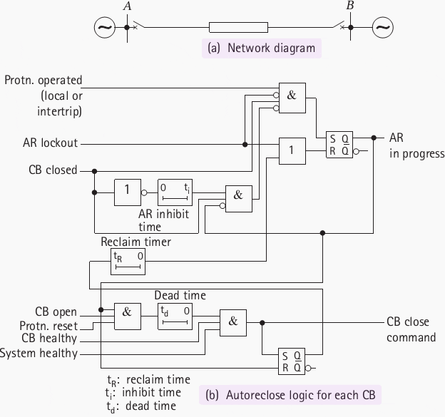
The sequence of operations of a delayed auto-reclose scheme can be best understood by reference to Figure 1. This shows a transmission line connecting two substations A and B, with the circuit beakers at Aand B tripping out in the event of a line fault.
It is therefore usual practice to incorporate a synchronism check relay into the reclosing system to determine whether auto-reclosing should take place.
After tripping on a fault, it is normal procedure to reclose the breaker at one end first, a process known as ‘live bus/dead line charging’. Reclosing at the other and is then under the control of a synchronism check relay element for what is known as ‘live bus/live line reclosing’.
Example
For example, if it were decided to charge the line initially from station A, the dead time in the auto-reclose relay at A would be set at, say, 5 seconds, while the corresponding timer in the auto-reclose relay at B would be set at, say, 15 seconds. The circuit beaker at A would then reclose after 5 seconds provided that voltage monitoring relays at A indicated that the busbars were alive and the line dead.
With the line recharged, the circuit breaker at B would then reclose with a synchronism check, after a 2 second delay imposed by the synchronism check relay element.
If for any reason the line fails to ‘dead line charge’ from end A, reclosure from end B would take place after 15 seconds. The circuit breaker at A would then be given the opportunity to reclose with a synchronism check.
Synchronism Check Relays
The synchronism check relay element commonly provides a three-fold check:
- Phase angle difference
- Voltage
- Frequency difference
The phase angle setting is usually set to between 20° – 45°, and reclosure is inhibited if the phase difference exceeds this value. The scheme waits for a reclosing opportunity with the phase angle within the set value, but locks out if reclosure does not occur within a defined period, typically 5s.
A voltage check is incorporated to prevent reclosure under various circumstances. A number of different modes may be available. These are typically undervoltage on either of the two measured voltages, differential voltage, or both of these conditions.
The logic also incorporates a frequency difference check, either by direct measurement or by using a timer in conjunction with the phase angle check. In the latter case, if a 2 second timer is employed, the logic gives an output only if the phase difference does not exceed the phase angle setting over a period of 2 seconds. This limits the frequency difference (in the case of a phase angle setting of 20°) to a maximum of 0.11% of 50Hz, corresponding to a phase swing from +20° to -20° over the measured 2 seconds.
While a significant frequency difference is unlikely to arise during a delayed auto-reclose sequence, the time available allows this check to be carried out as an additional safeguard.
As well as ‘live bus/dead line’ and ‘live bus/live line’ reclosing, sometimes ‘live line/dead bus’ reclosing may need to be implemented. A numerical relay will typically allow any combination of these modes to be implemented. The voltage settings for distinguishing between ‘live’ and ‘dead’ conditions must be carefully chosen.
In addition, the locations of the VT’s must be known and checked so that the correct voltage signals are connected to the ‘line’ and ‘bus’ inputs.
Reference: Network Protection & Automation – Areva


Pole mount auto recloser electric circuit for controller design and closing tripping circuit calculations.