
Estimated Study Time: 12 minutes
Delta-Star Connection of Transformer
The Delta-Star transformer connection is utilized to increase voltage levels and is frequently applied at the end or beginning of high-tension power transmission systems. The primary is configured in a delta arrangement, while the secondary is arranged in a star configuration, enabling a three-phase four-wire system at the secondary level. The secondary voltage supplied to the load is √3 times the primary voltage connected in delta configuration.
The load and secondary currents will be identical because they are part of the same series circuit. The Delta-Star connection offers three single-phase circuits at both lower and higher voltages, along with one three-phase circuit at greater voltage, enabling the supply of both single and three-phase loads.
Dual voltages are achieved with a delta-star arrangement. Low single-phase voltages are achieved by connecting between any phase and ground. Higher single-phase voltages are achieved by interconnecting any two phases. Connecting all three phases to the load delivers three-phase voltage.
Analogous to the star-delta configuration, the Delta-Star connection induces a 30-degree phase difference between the primary and secondary line voltages. This connection prevents the parallel operation of delta-delta and star-star transformers due to the phase difference between primary and secondary voltages.
In this type of connection, the primary connected in delta fashion while the secondary current is connected in star.
Figure 1 – Delta-Star Connection of Transformer

The main use of this connection is to step up the voltage i.e. at the begining of high tension transmission system. It can be noted that there is a phase shift of 30° between primary line voltage and secondary line voltage as leading.
Figure 2 – Phase shift of 30° between primary line voltage and secondary line voltage

Key Points of Delta-Star Voltages
As primary is connected in delta:
- Line voltage on primary side = Phase voltage on Primary side
- Now Transformation Ration (K) = Secondary Phase Voltage / Primary Phase Voltage
- Secondary Phase Voltage = K × Primary Phase Voltage
As Secondary is connected in Star:
- Line voltage on Secondary side = √3 X Phase voltage on Secondary side. So,
- Line voltage on Secondary side = √3 × K × Primary Phase Voltage.
- Line voltage on Secondary side = √3 × K × Primary Line Voltage.
- There is s +30 Degree or −30 Degree Phase Shift between Secondary Phase Voltage to Primary Phase Voltage
Watch Video – Delta and line voltage relationship in Delta-Star connection
Advantages of Delta-Star Connection
Advantage #1 – Cross section area of winding is less at Primary side:
On primary side due to delta connection winding cross-section required is less.
Advantage #2 – Used at Three phase four wire System:
On secondary side, neutral is available, due to which it can be used for 3-phase, 4 wire supply system.
Advantage #3 – No distortion of Secondary Voltage:
No distortion due to third harmonic components.
Advantage #4 – Handled large unbalanced Load:
Large unbalanced loads can be handled without any difficulty.
Advantage #5 – Grounding Isolation between Primary and Secondary:
Assuming that the neutral of the Y-connected secondary circuit is grounded, a load connected phase-to-neutral or a phase-to-ground fault produces two equal and opposite currents in two phases in the primary circuit without any neutral ground current in the primary circuit.
The neutral of the Y grounded is sometimes referred to as a grounding bank, because it provides a local source of ground current at the secondary that is isolated from the primary circuit.
Advantage #6 – Harmonic Suppression:
The magnetizing current must contain odd harmonics for the induced voltages to be sinusoidal and the third harmonic is the dominant harmonic component. In a three-phase system the third harmonic currents of all three phases are in phase with each other because they are zero-sequence currents. In the Y-Y transformer connection, the only path for third harmonic current is through the neutral.
In the ∆ -Y connection, however, the third harmonic currents, being equal in amplitude and in phase with each other, are able to circulate around the path formed by the ∆ connected winding. The same thing is true for the other zero-sequence harmonics.
Advantage #7 – Grounding Bank:
It provides a local source of ground current at the secondary that is isolated from the primary circuit. For suppose an ungrounded generator supplies a simple radial system through ∆-Y transformer with grounded Neutral at secondary as shown Figure. The generator can supply a single-phase-to-neutral load through the -grounded Y transformer.
Let us refer to the low-voltage generator side of the transformer as the secondary and the high-voltage load side of the transformer as the primary. Note that each primary winding is magnetically coupled to a secondary winding.
The magnetically coupled windings are drawn in parallel to each other:
Figure 3 – Magnetically coupled windings

Through the second transformer law, the phase-to-ground load current in the primary circuit is reflected as a current in the A-C secondary winding. No other currents are required to flow in the A-C or B-C windings on the generator side of the transformer in order to balance ampere-turns.
Advantage #8 – Easy Relaying of Ground Protection:
Protective relaying is MUCH easier on a delta-wye transformer because ground faults on the secondary side are isolated from the primary, making coordination much easier. If there is upstream relaying on a delta-wye transformer, any zero-sequence current can be assumed to be from a primary ground fault, allowing very sensitive ground fault protection.
On a wye-wye, a low-side ground fault causes primary ground fault current, making coordination more difficult. Actually, ground fault protection is one of the primary advantages of delta-wye units.
Watch Video – Comparison of delta and star windings
Disadvantages of Delta-Star Connection
In this type of connection, the secondary voltage is not in phase with the primary. Hence it is not possible to operate this connection in parallel with star-star or delta-delta connected transformer.
If secondary of this transformer should be paralleled with secondary of another transformer without phase shift, there would be a problem.
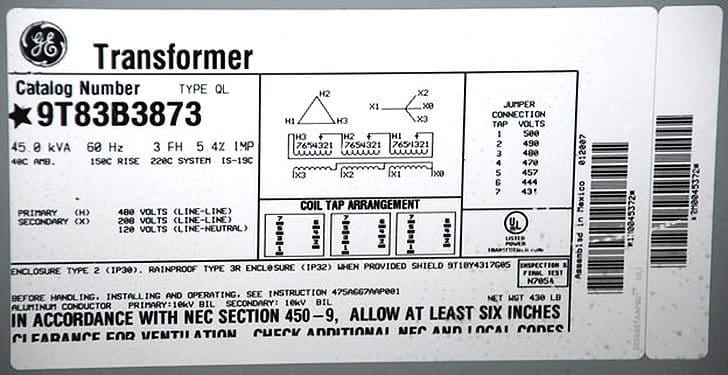
Figure 4 – Nameplate of a transformer with a Delta-Star winding configuration
Applications of Delta-Star Transformers
1. Commonly used in a step-up transformer
As for example, at the beginning of a HT transmission line. In this case neutral point is stable and will not float in case of unbalanced loading. There is no distortion of flux because existence of a Δ -connection allows a path for the third-harmonic components.
The line voltage ratio is √3 times of transformer turn-ratio and the secondary voltage leads the primary one by 30°. In recent years, this arrangement has become very popular for distribution system as it provides 3- Ø, 4-wire system.
2. Commonly used in commercial, industrial, and high-density residential locations
To supply three-phase distribution systems. An example would be a distribution transformer with a delta primary, running on three 11kV phases with no neutral or earth required, and a star (or wye) secondary providing a 3-phase supply at 400 V, with the domestic voltage of 230 available between each phase and an earthed neutral point.
Distribution transformers constitute the most common and diverse kind of transformers used within the energy distribution network. Approximately 700,000 distribution transformers are present in the public electrical supply system managed by the Regional electrical Companies, with a comparable quantity placed in industrial facilities.
Their sizes vary from approximately 15 kVA, 3.3/0.415 kV to 12.5 MVA, 11/3.3 kV, with the majority being under 2000 kVA and an average rating of roughly 800 kVA.
Useful Guide – Distribution transformers analysis and maintenance practices
Distribution transformers analysis and maintenance practices
3. Used as Generator Transformer
The ∆-Y transformer connection is used universally for connecting generators to transmission systems because of two very important reasons.
First of all, generators are usually equipped with sensitive ground fault relay protection. The ∆-Y transformer is a source of ground currents for loads and faults on the transmission system, yet the generator ground fault protection is completely isolated from ground currents on the primary side of the transformer.
Second, rotating machines can literally be.
Further Study – Managing power transformers in service: The most important economic aspects
Managing power transformers in service: The most important economic aspects
Related electrical guides & articles


Jignesh Parmar
Electrical Middle management professional having more than 22 years rich and dynamic experience in Project Execution / Project Management / Designing / Maintenance diversifies from Electrical Power Transmission (400KV/220KV/66KV)- Distribution(11KV/220V) to Lifts-HVAC-Ventilation-Fire Fighting-Fire Alarm-Lifts-CCTV-Stack Parking Works (High Rise Buildings, Townships, Shopping Complex, Commercial Complex, School, Temple).Profile: Jignesh Parmar

Need transpromer in assam
Hello Sir,
I have a 0.415/11KV delta_star step up transformer to meter from the LV side.
Does it make sense to pick the HV side star point as the neutral for a 3Phase 4wire connection of the meter?
Does it have any effect?
ours requested a 3-phase padmount 480V delta transformer to connect a 3-phase 480V pump motor. These are rare and it is unfeasible for us to stock, so we decided to provide them with a 3-phase 480Y/277V connection.
Has anyone experienced any problems with connecting a 3-phase 480 volt delta motor w. a 3-phase 480Y/277V xfmr? The motor has a soft start and a breaker to protect from motor faults (phase imbalance). The motor is getting 480 volts per phase.
My question is Y transformer can feed delta motor since they have same voltage rating
What is the current flow in primary winding if the secondary 1 & 2 windings draw 200A each for Dd0yn11 dry type transformer for 12-Pulse VFD system?
A single-phase fault on the red phase with I = −3 A gives
Ip = In = Io = −3
3 A.
Assume that we can isolate this fault by a star-delta transformer,
thus forcing Io = 0, and calculate the phase currents.
A 3 phase transformer having line-voltage ratio of when 240 V/ 11kV is
connected in star-delta and protective transformers on the HT side have a current
ratio of 20/14. What must be the ratio of the protective transformers on the LT
side?
In Delta-Start Distribution transformer, primary cable connection can be done with earthed cable?
ideal delta-wye xfrm & no load on transformer (480-208/120), for a L-G fault on the secondary side, what would be the line fault current flow on the primary which only involves the A-B primary winding?
Sir, its my heartiest honour to you. Sir I’m a electrical engineer n doing a govt. Job. I have Two Dyn11 11000/433 Volt Transformers with same X/R ratio. One already in service. Just recenty, I connected the 2nd transformer to 11kv side indoor metalclad switchboard for parallel operation. Phase sequence in secondary 433 Volt side of both transformer is ok. After testing the voltage on 433 Volt side of both x’mer thro. Test lamp, it’s showing voltage between same phases of two xmer. Hence polarity of both are NOT correct. Both transformers are connected thro.sealed pack cable box. Shutdown of transformer already in service is NOT permitted. I have only option to change the 11kv side cable connection of 2nd transformer. How to change the 3 leads of delta side of 2nd xmer to match the polarity with 1st xmer. Regards.
Hi! I can changes the connection of factory of the secondary side in dry trafo. Of star to delta. What happens?
Regards
TRANSFORMER, STEPDOWN, THREE PHASE, DRY TYPE, 5 KVA, DELTA/STAR, PRIMARY: 460 V, SECONDARY: 380 & 220V, INDOOR TYPE.
Dear Mr.Jignesh
Happy new year.
I have seen your name and articles in the website and got interest to receive some right suggestions fro you.
We are a engineering company a do electrical business in Bangladesh.Recently we are talking a customer for their
Textile Spinning project.The criteria are as follows:
Primary source 6 nos 1500 KW Gas Generator( 415 V,3 phase 4 wire system).Customer need transfer this 8 MW
Load from Generator house to main factory building.Distance between Generator Hose to main factory is 800 meters. So we planned to transfer 8MW Generator power from Generator house to factory building by 8 nos 2500KVA Cast Resin Dry type Transformer(2500 KVA,11/0.415V,50Hz).We planned as follows:
a) 6 nos 1500KW Generator power will come to Main panel,where 6 nos Generator will be synchronised.
b) From mail LT panel we planned to take power by 4 nos 5000Amp Air circuit Breaker(415 V,50Hz)
c) we planned to use 4x2500KVA Step up Transformer through 4 nos 11KV HT Switchgear as incoming and
1 nos 11KV Switchgear as out going by 12KV HT cable to factory side.
d) we planned 1 no 11KV HT panel as incoming and 4 nos 11KV HT panel for 4 nos 2500 KVA Step down
Transformer to Factory LT panel.
Now we please confirm us that we are using
a) 4 nos 2500 KVA step up Transformer, Yd1( primary side 415 V, Delta connection),Secondary side 11KV star connection with neutral grounded)
b) 4 nos 2500KVA step down transformer Dyn11(Primary side 11KV and Secondary side 415v with neutral grounded).Power will come factory LT panel and from there power will go through BBT(Bus Bar Trunking System)
Please confirm us our selection of transformer is ok.Because 4 nos step up transformer will wok as parallel operation.On the other side 4 nos step down transformer will also work as parallel.
Considering vector group and other factor of transformer parallel operation,above Transformer selection is ok
or if you have any recommendations pls let us know.
Best Regards
Engr.Kazi Anwar Hossain
Managing Director
KDH Engineering Ltd
Dhaka,Bangladesh
Mob:+8801713004662
Pls give the reply
Hello Sir,
Can you please give the solution of this?
How do I get 230V and 15 amps three stable AC outputs from three-phase 440V/415VAC input?
Sir what’s cause dpu failure instantly on control room
Hi Sir
Just want to know if a 400V supply from a generator is connected to a step up transformer400v/11000V. What would be the vector type of the transformer and do you connect the neutral cable?
Regards
Justin Low Thion
Sir,
I have a question what is the reason for fault occur in load side fuse in transformer
For a Y-D Transformer , if the D side gets grounded what will happen.?
if there is a second grounding what will happen.?
sir,
I have 500 kva outdoor transformer, I want to change tapping for the same,
please let me know how to calculate output voltage of the LT side.
Hi Jignesh,
I have a delta/zigzag+N (DZno) isolation transformer (415v/440V) connected to any IT system (floating / unearthed). My question is, do I need to terminate the neutral to ground, even though the transformer is connected to an IT system? or do I not connect the neutral?
The transformer enclosure is grounded.
Hi , I have a doubt , for 1000 KVA transformer, the cable to main panel we are using is 1Core 630 mm2 of two runs for each phase and one run for neutral, ie total 7 runs , the distance between panel and transformer is 45meter , Can you suggest if any problem in doing the same? What will be maximum current capacity of mentioned above cable?
Hi Parmar, i have a medium voltage system comprising of four 2188kVA, 11kV gas generator with star point synchronized together on a HT bus with two 2250KVA, 415V diesel sets connected to two 2.5MVA (0.4/11KV) step up delta/star transformer. the two diesel sets will be synchronized at LV side and stepped up to 11kV to be synchronized on the 11 KV bus. do i need to connect the neutral cables of the 11KV gas generator and 415V of the diesel generators, because if the two diesels are started and synchronized at 11KV bus, the 11KV gas generator can sync with them, but if the gas is started first, the diesel set sees an inbalance bus reference. please what can cause this inblance?
Is there any problem if we connect YNd1 instead YNd11 in generator step up Tranformer , and UAT WITH Dyn11 instead Dyn1.
what will be problem if secondary side (LOAd side winding leading) is it mandotory to design always secondary winding load side to be lagging ? please confirm.
Sir what is instantaneous current in 3 wire 2 phase transmission system and how instantaneous current differ from line current. Plz reply
I have a 100kva trf and want to use it for step up from 400v to 3300 volt, but input is delta and ht side is star, with a neutral.
What do I do with neutral on input side and what do I connect to neutral terminal on output side.
Sir above we said delta(primary) star(secondary) connection T/f is a step up transformer but 11kv/440v is a step down voltage so how can said star delta connected T/f is a step up transformer
I have a standby DG 3ph-380V, 1250kVA, 1800rpm, 60 Hz with a Star connection, while its Neutral is connected to the Ground. This Generator is supposed to provide 33kV via Step up Transformer to an assembly of 33kV switchgears containing Vacuum type circuit breaker.
Please tell me, what is the best configuration for the Transformer in this case. Note that the Step up transformer is rated to be 1250kVA.
Which side is to be Star and which to be Delta for this step up transformer?
And How the earthing connections should be done?
Please provide comprehensive response.
Thanks
Irfan
sir,
star connection 3phase supply of 400V r y b conductor. Then r in phase Voltage ,r & y in phase voltage,
who to calculate When r y connection in 400V and r y b is also in 400V why.
what effect in transformer if we are incoming supply 2 phase fed in a 3phase 25KVA delta -star 6.6/110V transformer.
Sir;
how Can we detect theft in any type of line
sir what is the effect of third harmonic in step up and step down transformer
Sir.
In Delta-star connection of a transformer if a phase is faulty or switched off,then what will happen??
We are having Biogas genrtor connected in star feeding to delta connected step up transformer.Protection system frequently trips on earth fault.On checking we could not find any problem.Kindly give probable reason/suggestion.
Nitin
Sir I have a doubt regarding the power house situation which is similar to your above described article. Could you share you email id inorder to forward my material?
sir, suppose 11kv/400v delta star config transformer fed with two phase 11kv assume one phase ht fuse blown out .on secondary side we get full voltage in one phase and low voltage at other two phase .my question is this due to the reason that one phase get full 11kv voltage wheras other two phase of primary get half of the 11 kv voltage .if we draw the diagram it seems this way ,pls explain me
3 phase transformer primary side 1 phase missing what will happen in secondary side?
if a 3 phase transformer is connected delta at primary and wye at secondary then the fuse cut-out at the tapping pole suddenly opened is there a tendency that the line that is open has still power coming from the transformer ?the cut-out of the 3 phase transformer does not open..
what is the problem if showing of 45 kv transformer secondary side L1,L2,L3 is ground with
earth, when primary 480 v delta connection & secondary connection in star phase to phase 220 v, phase to neutrail 127 v
can a phase of an individual generator connected to the neutral of national grid whiles the grid is off? what happend then?
Would mind mention the other reason for using delta-star connection for the generator transformer
In a distribution overhead network with Delta Star Transformers for 11kV/433V system, can we use single phase MCCBs for transformer protection?
What will happen in case of a L-L fault trips the MCCBs feeding the two faulted phases?
state limitation on direct on line starting
state why a motor designed for delta connection windings must not be connected to run on star connection
Can you please explain, if one of the transformers has it’s start point disconnected from earth. How does this affect the fault level? Can you please explain if the start star transformers is replaced by delta star transformer. How does this affect the fault level.
Thank you very much.
ON A STEP UP TRANSFORMER DELTA / STAR 220/3/ TO 415/3/
WITH THE NEUTRAL TIED WITH GROUND , WOULD THIS AFFECT THE TEMPERATURE
OF THE TRANSFORMER AND THEREFORE, CAN CAUSE THE IT TO OVERHEAT?
Just need to know that incase of any transformer with priamary in delta and secondary in earthed star , then incase of ground fault on delta side , will there be any fault current electrically pass through ground of star via grounded transformer tank and then some portion passes through earth fault protection of star side and some portion moves back via the ground path where the original fault occurs… ? Is there any practical example in field where such phenomena has spuriously operated the EF relay on star side due to fault on delta side. ?? remember that I am assuming that only that portion of EF will pass which will have electrically connected between primary and secondary through earth connection ,, there will be no flow via maganetically coupled windings within transformer,,,
Hello
can you please explain how and in what configurations does the harmonics get cancelled. it circulates in delta , so is it considered cancelled or it goes through N in star ,and hence is eliminated in star connection.
Thanks a lot.
Regards
Manish
Dear Mr. Jignesh,
First of all would like to thank you for giving such a great insight of delta star trafo. i had a question on the same. If 800kVA, 415V/11kV step up trafo is used, where LV supply is fed by 415V DG sets. The incomer to trafo from DG is 1600Amp, FP, ACB. my question is, since trafo is delta star that means at LV side which is delta connected side its 3phase, 3wire system. hence the incomer to trafo LT side shud be 1600Amp,TP ACB. but incase FP ACB is used than the Neutral is grounded or what exactly is the procedure of sizing switchgear.
Regards’
Shanam