
Estimated Study Time: 22 minutes
Changeover Logic Design
In any industry/plant, the operations rely heavily on interruption free supply of power to meet the targets of production. As a result, we see emergency generators, UPSs or renewable energy sources to save us from complete shutdown. This back-up or redundancy approach is implemented at every stage of the power supply network.
 Design of Auto/Manual Changeover Logic Between Two Busbars Within a Substation
In many places, we see the design of a substation with two separate busbars being fed from two different transformers and sharing the load between them.
In case of failure of either of the transformers, busbars, cables or their associated switchgear, a changeover option between the two will be at hand to keep the loads up and running.
In line with the discussed scenario, we will look at the design of auto-manual changeover logic between two busbars within a substation in this article.
- Single Line Diagram of the Substation
- Closing of Breaker 52A-1 with Bus tie 24 and Breaker 52B-1 Opened
- Auto/Manual Changeover Between Busbars
- Manual Changeover
- Automatic Changeover Between the Busbars
- Energization of Automatic Changeover Relay 83
- Tripping of Breaker 52A-1
- Closing of Bus tie Breaker 24
- Reclosing of Breaker 52A-1 After Normalization of PC1A-1 Voltages
- Reclosing of Breaker 52A-1 With Synchronization Without Interruption
- Tripping of Bus tie Breaker 24
- Reclosing of Breaker 52A-1 Without Synchronization with Interruption
- Tripping of Bus tie
- Tripping of Breaker in Case of Overload Protection Activation
- Sensing of Short Circuit
- Conclusion
- Attachment (PDF) 🔗 Download ‘Issues of false tripping, blinding of protection and lost of coordination in networks with distributed generation’
1. Single Line Diagram
The simple layout diagram of a substation is provided below in which two step-down transformers TR1 and TR2 are fed from a high voltage line. These transformers are then connected to their respective busbars PC1A-1 and PC1B-1 through low-voltage circuit breakers 52A-1 and 52B-1.
Both busbars share the total load i.e. large motor feeders, MCC cubicles and auxiliary supply panels (ASPB) between them.
Figure 1 – Single line diagram of the substation we’ll discuss
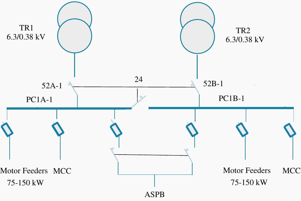
We’ll discuss in detail the following scenarios taking the busbar PC1A-1 and its breaker 52A-1 as an example; same will apply for the busbar PC1B-1.
- Closing of breaker on bus PC1A-1 with bus tie 24 and breaker 52B-1 opened
- Manual changeover between the busbars
- Auto changeover between the busbars
- Reclosing of Breaker 52A-1 with Synchronization
- Reclosing of Breaker 52A-1 without Synchronization
- Tripping of breaker 52A-1 in case of Overcurrent Protection (51)
- Blocking of changeover in case of short circuit
Following protections make up the switchgear of this low-voltage substation.
- Instantaneous overcurrent relay (50)
- Inverse time overcurrent relay (51)
- Automatic changeover relay (83)
- Tripping relay (86)
- Lockout relay (94)
- Undervoltage relay 90%
- Undervoltage relay 50%
There is also one synchronization relay (25) for synchronizing the two busbars. In case of the substation being used here as an example, listed below are the threshold values of the parameters beyond which the sync relay 25 doesn’t permit the synchronization of the two busbars.
Table 1 – Threshold values of the parameters
| Parameters | Maximum Difference |
| Voltage | 6.9 V |
| Frequency | 0.1 Hz |
| Phase Angle | 10° |
2. Closing of Breaker 52A-1 with Bus tie 24 and Breaker 52B-1 Opened
Attached is the drawing of substation incoming breaker 52A-1 on busbar PC1A-1. Understanding of this drawing applies to the drawing of incoming breaker 52B-1.
The contacts marked yellow remain in the state as shown in the drawing when the breaker 52A-1 is open. Similarly, the position of contacts in blue is when the breaker 52A-1 is racked out. Similar is the case of breaker 52B-1. The contacts marked in grey are in the path to the closing coil of the circuit breaker 52A-1.
Figure 2 – Drawing of substation incoming breaker 52A-1 on busbar PC1A-1
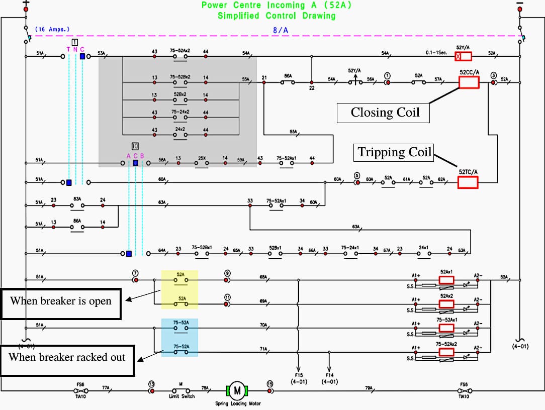
Let’s discuss the state of each contact,
- 75-52AX2 – Open when breaker 52A-1 is racked in
- 75-52BX2 – Open when breaker 52B-1 is racked in
- 52BX2 – Close when breaker 52B-1 is open
- 75-24X2 – Open when bus tie 24 is racked in
- 24X2 – Close when bus tie is off
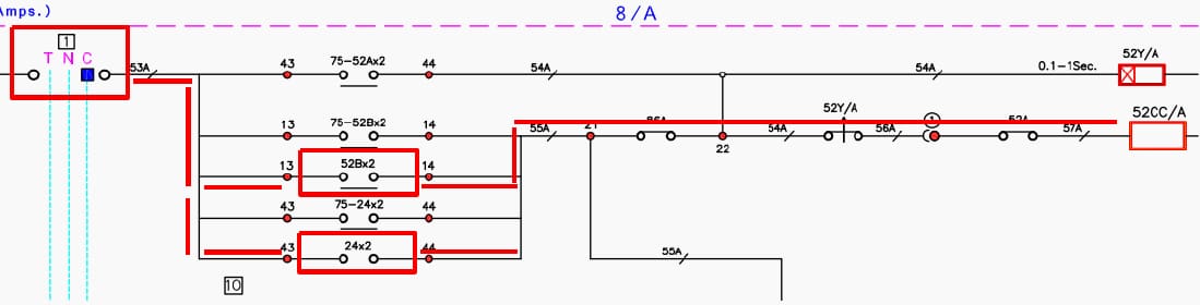
However, if bus tie 24 and breaker 52B-1 are both closed which means the load of busbar PC1A-1 is being shared by busbar PC1B- through bus tie then we cannot manually close 52A-1 breaker because of absence of synchronization relay in this path.
Figure 3 – Breaker 52A-1 can be closed manually using the TNC switch through contact 52BX2 and 24X2
3. Auto/Manual Changeover Between Busbars
Changeover between busbars can be carried out either manually without interruption or on auto with interruption.
3.1 Manual Changeover
Manual changeover occurs without interruption with the help of a unit sequence switch. This changeover is performed by personnel which means that either of the busbars is being taken down for maintenance or any other issues related to its switchgear or transformer and it allows us the luxury to transfer the load of this busbar on the other without interruption.
Let’s see how we can transfer busbar PC1A-1’s load on busbar PC1B-1 with manual changeover which takes place as per the following conditions as shown in the following flowchart.
Figure 4 – Flowchart with conditions for transfering busbar PC1A-1’s load on busbar PC1B-1
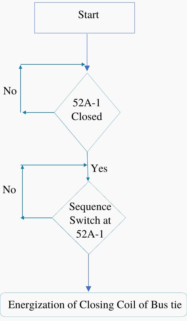
So, when all the conditions as per the above flowchart are met, following events take place:
- Signal to the closing coil of bus tie breaker 24 is initiated which means the two busbars will first be synchronized with the closing of bus tie breaker 24 through synchronization relay 25.
- Breaker 52A-1 will be tripped and entire load will now be on busbar PC1B-1.
Let’s see the following process as per the drawing.
3.1.1 Closing of Bus tie Breaker 24
From the attached drawing of bus tie breaker 24, we can see that the energization of bus tie breaker is permitted with the closing of synchronization relay contact 25X as highlighted in the red box. The two busbars will be synchronized.
Up next, the tripping of breaker 52A-1 will be executed just as the bus tie breaker 24 is closed.
Related electrical guides & articles


Umer Nasir
I am an electrical engineer specializing in electrical power, with experience in the operation and maintenance of Low- and Medium-voltage electric machinery and switchgear, life assessment testing, troubleshooting, and root cause analysis of various failures associated with electrical machinery.Profile: Umer Nasir
