
Estimated Study Time: 17 minutes
Power supply planning
When power supply systems for car manufacturing plant are planned, each individual problem can be faced in various ways: by means of technical solutions that feature specific technical advantages.
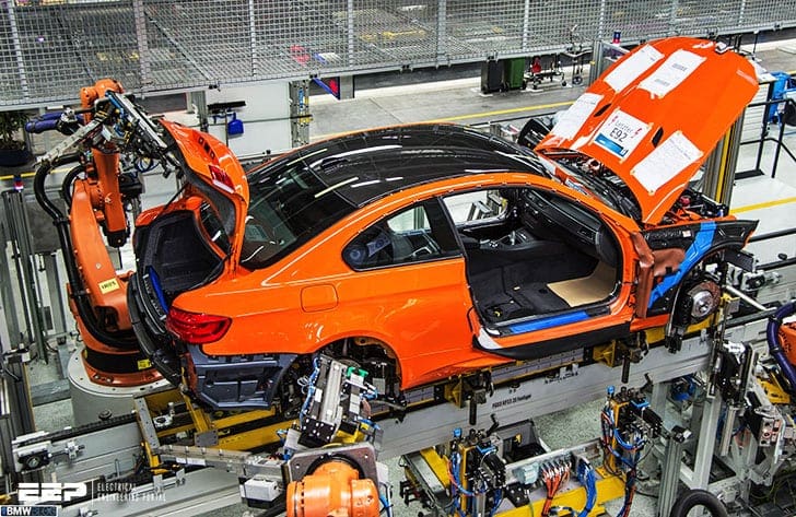 Design of primary and secondary power distribution in car manufacturing plants (BMW, VW...)
This means that both a thorough knowledge of the relevant industrial technology is required and comprehensive know-how about the equipment and systems under consideration.
This know-how will be detailed on the basis of process-related power supply planning for a car manufacturing plant.
Network and plant engineering solutions for the optimum fulfillment of requirements placed on the power supply of a car manufacturing plant will be demonstrated here.
Contents:
- Requirements to the power supply system set by the process
- Optimum power system and plant configuration
- Operating mode – Medium voltage (MV)
- Operating mode – Low voltage (LV)
- Process-dependent particularities for the design of subsystems
- Summary
1. Requirements to the power supply system set by the process
The process flow in an automotive manufacturing plant determines the requirements to the electric power system.
The following requirements shall be met:
- Covering a process-oriented power demand
- Ensuring a high degree of supply safety by mastering the (n-1) principle
- Ensuring high power quality in accordance with DIN EN 50160:2000-03 (properties of the supply voltage) and DIN EN 61000-2-4 (VDE 0839 Parts 2-4):2003-05 (EMC level)
- Ensuring a high degree of safety for man and machinery under normal operating conditions as well as under fault conditions
- High adaptability to changing manufacturing processes
- Reduction of operating costs due to low maintenance expense and low power losses
- Simple operatability and operator-friendly systems alike
In automotive manufacturing plants, a network configuration as shown in Figure 1 has proved its worth with regard to technically and economically efficient implementation of these requirements.

2. Optimum power system and plant configuration
The power supply for the production halls in a car manufacturing plant is distributed by means of medium-voltage load center systems.
The PEHLA-tested transformer load center substation (TS station), tested in accordance with DIN EN 61330 has proven itself as an economical and safe element in distributed power supply.
Protection for the TS stations, which are equipped with cast-resin transformers, is provided by a load switch-fuse combination which is rated and selected according to the criteria given in IEC 62271-105:2002-08 or DIN EN 60420 (VDE Part 303):1994-09.
The relevant standard for the selection of the high-voltage high rupturing capacity fuses (HV HRC fuses) is DIN VDE 0670-402 (VDE 0670 Part 402):1998-05.
3. Operating mode – Medium voltage (MV)
Most favorable operating mode from the point of view of power engineering is medium voltage (MV). The operating mode of the MV power system is determined by the type of neutral point connection.
The most important types of neutral point connection in MV systems according to DIN VDE 0101 (VDE 0101):2000-01 are as follows:
- Isolated neutral
- Ground fault compensation or resonant neutral grounding (RESPE)
- Low-resistant neutral grounding (NOSPE)
The following advantages are decisive for this trend:
- (n-1)-redundant network design allows selective disconnection of 1-pole faults
- Protective disconnection of the fault location is carried out without interrupting the power supply
- Clearly defined protective trippings and changes of the switching status enable integrated power automation
- Low-resistant grounded neutral operation (resistance) prevents high transient long-term operating overvoltages
- Danger of fault expansion and double ground faults is eliminated
- Short tripping times limit follow-up damages of ground faults at the fault location
The operating experience gathered with NOSPE networks used in plants of Volkswagen AG, Adam Opel AG and DaimlerChrysler AG confirms the advantages of low-resistant neutral grounding.
BMW AG is another automotive manufacturer that has decided in favor of low-resistant neutral grounding of the 20-kV power system to be installed in their new plant at Leipzig.
4. Operating mode – Low voltage (LV)
The system types suitable for operation as LV systems are defined in IEC 60364-1:2001-08 or DIN VDE 0100-300 (VDE 0100 Part 300):1996-01.
As far as the type of connection to ground of the system power source and the type of connection to ground of the conductive parts in the electric consumer system are concerned, distinctions can be made between IT, TT and TN systems.
Only at a lower level can a TN-S system be built with a separate neutral conductor (N conductor) and protective ground conductor (PE conductor).
Consequently, LV systems for the automotive industry have so far been designed exclusively as TN-C-S systems.
In a modern automotive manufacturing plant, too, higher requirements are placed on electromagnetic compatibility in order to prevent any negative impact on the production process by electromagnetic interference of communication and information technology systems.
An EMC suitable LV system with a continuously de-energized PE conductor must be designed as TN-S system. In multiple-supply LV systems, a TN-S system is only feasible if the PEN conductors or the individual supply circuits can be grounded at a central point.
At present, the form of design represented in Figure 3 is not backed up by national or international standards. Until a valid standard has been adopted, it is the sole responsibility of the switchgear installer or plant operator.
So far, only Adam Opel AG has operated a multiple-supply LV system as TN-S system.
5. Process-dependent particularities for the design of subsystems
5.1 Press shop
In the press shop, a large number of motorized press drives are installed for forming metal sheets into body parts. The individual power output of these drives is relatively high compared to the total power demand of the press shop and it puts a surge type, intermittent burden on the power system.
Another system perturbation is caused by the thyristor controllers of the press drives, as they generate harmonics of the vth order.
An example of how to meet this power quality requirement is shown in Figure 4.
Another requirement for the LV system in the press shop is for the permissible compatibility levels for harmonic contents to be observed as defined in DIN EN 61000-2-4 (VDE Parts 2-4):2003-05.
To maintain these levels, the compensation system of the switchgear substations must normally be inductor-type.
In practice, inductor-capacitor units with a choking degree between p = 6% and p = 7% are mainly used.
5.2 Body shop
Connection of the welders in the 400 V system of the body shop is carried out in groups by a symmetric distribution to the phase conductors L1-L2, L1-L3, L2-L3 (Figure 5).
Due to their intermittent operating mode, the machines for welding the body parts connected in the circuit do not constitute a continuous load.
Therefore, the equipment in the welding circuit must be rated according to its thermal equivalent current.
For rating the welding network, the thermal equivalent current is, however, merely of minor importance.

What is more important are the voltage dips caused by the accidentally overlapping welding pulses. The probability calculation of these voltage dips is again based on the binomial distribution.
To apply the Bernoulli formula, the different welding machine types are combined into one uniform equivalent welding machine with an identical peak welding current Iw, the identical power factor cosϕ and the same relative ON period OP.
This probability peak load calculation provides the required indicator for evaluating the power supply quality in the body shop.
In the body shop, compensation can normally be made non-choked. For the non-choked compensation method, observance of the permissible compatibility level for harmonic contents has been verified by measurements in several 400 V welding networks in the automotive industry.
A favorable solution in terms of power engineering proves to be the use of capacitors with a rated voltage of 480 V ≤ Um ≤ 525 V.
5.3 Paint shop
Paint shop processes are characterized by high load densities and long ON periods of the consumers. What is particularly typical is the negative impact on power quality caused by the rectifiers for the electro-dipcoating or cataphoretic painting process.
In order to relieve the LV system from harmonic impact, these rectifiers are preferably supplied directly from the MV system via separate transformers.
This includes the uninterruptible handling of the single fault by a protective disconnection of the fault location from supply.
Cast-resin transformers at the TS station provide an instantaneous standby or “hot” redundancy to handle such single faults. In addition, a standby supply is provided for sensitive and fail-critical consumers.
5.4 Final car assembly
The connected power of the consumers in the final car assembly is relatively low as compared to the nominal power of the supplying transformers. For this reason, the maximum power demand of all consumers in the grid is important for system rating.
Power demand is largely influenced by the simultaneity factor g, the degree of utilization a, the power factor cos ϕ and the efficiency η.
In the final assembly plant section, a large proportion of the nonlinear consumers is single-phase connected between phase conductor (L1vL2vL3) and neutral conductor (N). In this type of connection, all current harmonics of the order v that can be divided by 3 add up in the neutral conductor N.
The current harmonic whereby v = 3 is particularly distinctive.
To prevent thermal overload caused by current harmonics, the phase conductors (L1, L2, L3), neutral conductor (N) and PEN conductor of the TN-C-S system (Figure 2) or TN-S system are designed with identical cross sections as a matter of principle.
6. Summary
The load center network in combination with a TN system consisting of busbar trunking systems is the ideal network configuration for the power supply of production halls in an automotive manufacturing plant.
Currently, there is no binding standard for the design of a multiple-infeed LV system as TN-S system.
There is only a unanimously optimum solution for the design and operation of the supply networks. The rating of the supply networks for the processes handled in the production halls results in engineering differences such as the number and size of the supplying transformers and the method of compensation.
Reference // Totally integrated power by Siemens
Related electrical guides & articles


Edvard Csanyi
Hi, I'm an electrical engineer, programmer and founder of EEP - Electrical Engineering Portal. I worked twelve years at Schneider Electric in the position of technical support for low- and medium-voltage projects and the design of busbar trunking systems.I'm highly specialized in the design of LV/MV switchgear and low-voltage, high-power busbar trunking (<6300A) in substations, commercial buildings and industry facilities. I'm also a professional in AutoCAD programming.
Profile: Edvard Csanyi

Hi, I am Electrical Engg; and work construction of factory, building,solar. . Pls share knowledge
hi edvard how r u I’m senior electrical engineer “yadollah khodarahmi” working as supervisor in power plant and would like to cothinking about industrial problems r u ready ?
thank you
best regards y.khodarahmi