
Estimated Study Time: 24 minutes
Emergency Generator as Back-up Source
Many utilities have diesel generators added to their energy mix to act as an emergency back-up source when a power shutdown occurs. These emergency generators cannot thwart the entire system from going down but are critical for safe shutdown of the plant.
 Design of Emergency Diesel Generator Control Circuit Logic for Integration with the Utilities
For instance, in case of total power failure, some motors need to be operated for barring of shafts of compressors, pumps and turbines for preventing them from bowing. In such situations, emergency generators play a very significant role.
This article begins with a busbar scheme of emergency generators and the discussion of what happens if a power failure occurs. It continues with the logic of connecting emergency generator to the system.
Next, we’ll discuss the scenario after normalization of power system and what happens after the system has recovered from power failure, and the load is shifted back onto the main power source. Here, we’ll consider three different scenarios.
- Conclusion
- Attachment (PDF) 🔗 Download ‘Practical Guide to Electrical Testing of Power Transformers’
1. Busbar Scheme of Emergency Generators
Emergency generator is tied to the busbar to which the critical/emergency loads are connected as mentioned above. Normally, that busbar draws power from main generators/sources in the system and the emergency generator remains off.
But designing the entire logic of connecting and then disconnecting the emergency generator to the power system requires keeping in view a great many scenarios in order to prevent any mishap.
2. Auto/Manual Selection Logic
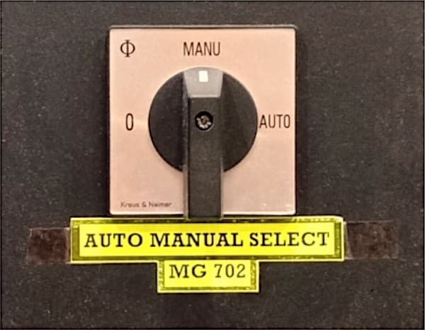
On the operator desk and/or in the field cabinet of emergency generator, there is an auto/manual selection switch.
As per the requirement of the utility, the logic of connecting emergency generator to the system is designed such way that when under voltages occur at the busbar having the largest power source connected to it, then the bus tie breaker connecting this busbar to the emergency busbar will automatically be opened (by disconnecting the emergency busbar from the entire system).
Then the breaker of emergency generator will be closed onto the emergency busbar. This is where the auto selection of emergency generator comes into play.
Figure 1 – Emergency Generator Auto/Manual Selector Switch
3. Example of a Power System
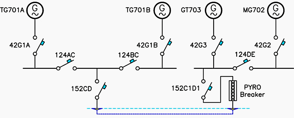
Below is the single line diagram of a power system implemented in a utility. There are a total of four generators, out of which three continuously feed the busbars A, B, C, D & E in synchronization. One is the emergency diesel generator which normally remains off.
Following nomenclature will be used for the elements of this power system,
- TG-701A and TG-701B for two steam-driven turbo generators
- GT-703 for a gas-driven generator
- 42G3 for gas-driven generator circuit breaker
- MG-702 for the emergency diesel generator
- 42G2 for emergency diesel generator circuit breaker
- Main busbar D
- Emergency busbar E
- Bus tie breaker 124DE
Also, power failure here would mean shutdown of both turbo and gas-driven units.
Figure 2 – Example of Power System of a Utility
3.1 Design of the Auto Selection Logic of Emergency Generator
Here, we’ll discuss in detail how the emergency generator will automatically be connected to the emergency busbar if a power failure occurs. As per the attached Figure 1, let’s see what happens when under voltages take place at bus bar D.
Figure 3 – Emergency generator automatic connection to the emergency busbar if a power failure occurs
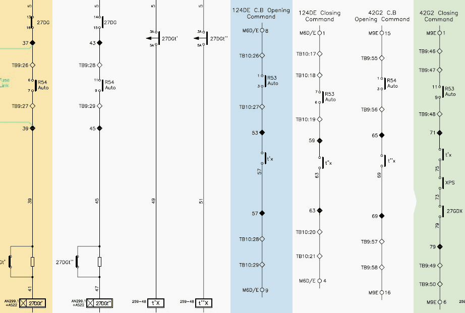
In the attached schematic diagram:
- 27DG is the contact of under voltage relay installed at main busbar D.
- R54 is the auto-selection contact of emergency generator, its scenario has been discussed above
- 27DGt’ and 27DGt” are on-delay timers whose contacts upon closing energize relays t’X and t”X
Now when under voltages occur at bus bar D, the contact of 27DG (marked in orange block) closes onto on-delay timer 27DGt’, following which the relay t’X is energized and its contacts close in two circuits:
- Firstly, the contact of relay t’X closes in bus tie 124DE opening circuit (marked in blue block)
- Secondly, the contact closes in 42G2 closing circuit (marked in green block)
Now let’s discuss in detail the schematic diagram of emergency generator breaker 42G2 closing on auto-selection.
Related electrical guides & articles


Umer Nasir
I am an electrical engineer specializing in electrical power, with experience in the operation and maintenance of Low- and Medium-voltage electric machinery and switchgear, life assessment testing, troubleshooting, and root cause analysis of various failures associated with electrical machinery.Profile: Umer Nasir
