Power plant design
A black start refers to the ability of a power plant to restart itself using its own resources in the event of a complete shutdown and isolation from external power sources. Initiating a black start at an industrial plant might be a straightforward process.
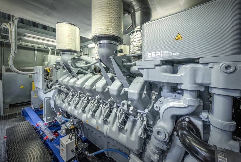
However, before we get into details, it is important first to discuss power plant designs and equipment.
1. Power plant design
The generators are usually designed with brushless excitation and incorporate permanent magnets. They are insulated with Class H materials and have a temperature rise of Class F, reaching 105°C over an ambient temperature of 40°C.
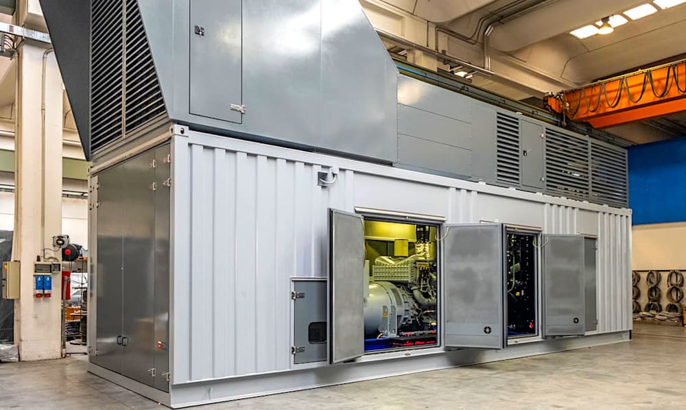
Units with a capacity of up to 2 MW can be specifically built to be put in movable containers. The container usually includes all the necessary electrical, control, fire protection, and mechanical equipment to allow the diesel generator (DG) set to function independently.
The configuration generally comprises of one cell for each generator, two breaker cells for the station service transformers, four to six feeders for power distribution, and a tie breaker.
Figure 1 – Containerized DG system

The power demand of the station service is supplied by the station service transformers and low voltage motor control centers (MCCs). An approximate estimation for the overall plant auxiliary load is around 5% of the total plant generating capacity.
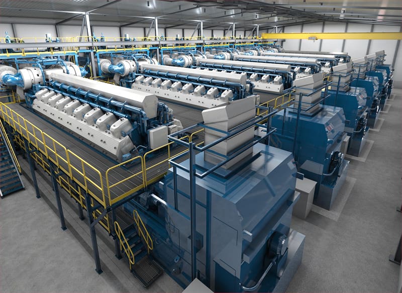
Plants that possess four to six or more engines are frequently encountered. The distance between the engines is 6 to 7.5 m (20 to 25 ft), measured from the center line of one engine to the center line of the other, and it varies depending on the breadth of the engine.
A loading/maintenance bay is permitted on the side of the main gate entry.
Figure 2 – Power plant engine room (the plant operates with six Wärtsilä 50SG gas engines having a combined net output of 108 MW)

The engine auxiliary bay is situated at the back of the engines, while the electrical area is positioned on the generator side, with a walkway or truck driving space separating the generators and MCCs. The primary medium voltage (MV) switchgear is situated in a distinct chamber adjoining the control room, all of which are positioned one level above the main floor.
The cabling, often of medium voltage, is arranged in trenches or cable trays in order to limit the number of cable crossings between the generators. The cables for the engine auxiliaries are installed on overhead cable trays located at the back side of the engines.
Both single-line diagrams in Figure 3 and Figure 4 contain producing units, GSUT, Generator step-up transformer; UAT, unit auxiliary transformer; SST, station service transformer; GCB, and generator circuit breaker.
Figure 3 – Power plant with smaller units
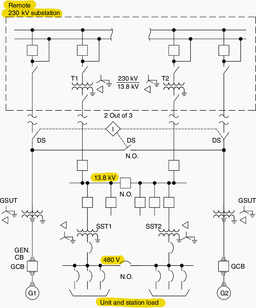

Figure 4 – Power plant, larger units
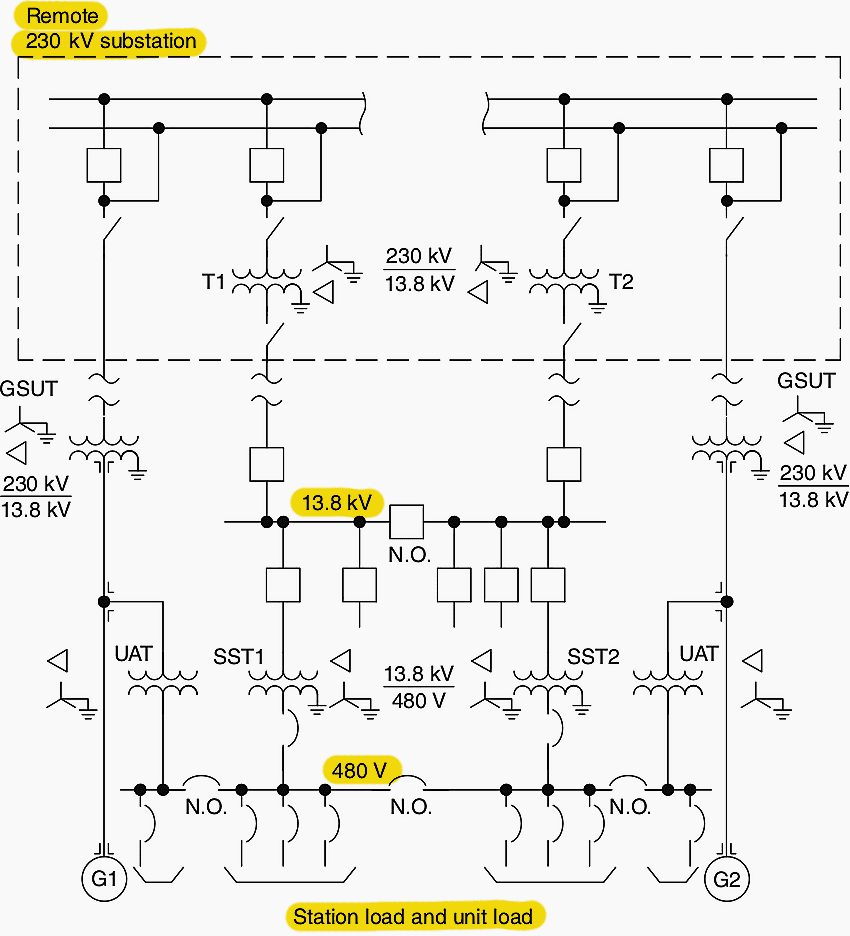

An alternative method employed for higher generator currents involves eliminating the use of a generator circuit breaker (GCB) and instead directly connecting the generators to the output transformers within the power plant. The transformers are then connected to the remote switchyard at high voltage (HV).
In this scenario, the process of synchronizing and switching the generator is carried out using remote switchyard breakers.
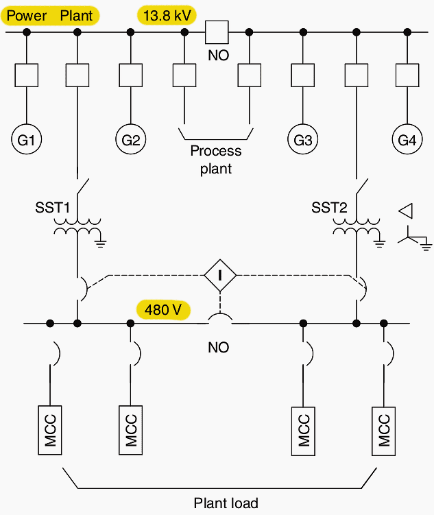
A plant single-line diagram for a diesel generating plant is completely different and shown in Figure below.
Figure 5 – Diesel generator plant basic single-line diagram

1.1 Generator grounding
Each generator is equipped with a single-phase distribution transformer to achieve high resistance grounding for a fault current of 5 A.
1.2 Plant automation
In-house generating plants are typically operated automatically, functioning independently without the need for human intervention. The control system will automatically adjust the number of units in response to the power demand in the plant, optimizing their operation within the most efficient range (80–110%).
The units typically operate with a droop of 3–4% in order to evenly distribute the load among them.
All necessary data, like events, alarms, analog information and disturbance data in Comtrade format can be accessed in System 800xA (see Figure 6).
Figure 6 – ABB’s 800xA System, the industry’s most intuitive system interface, provides a consistent method for accessing enterprise-wide data and for interacting with multiple applications from any connected workstation in the plant or office.
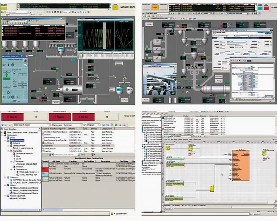

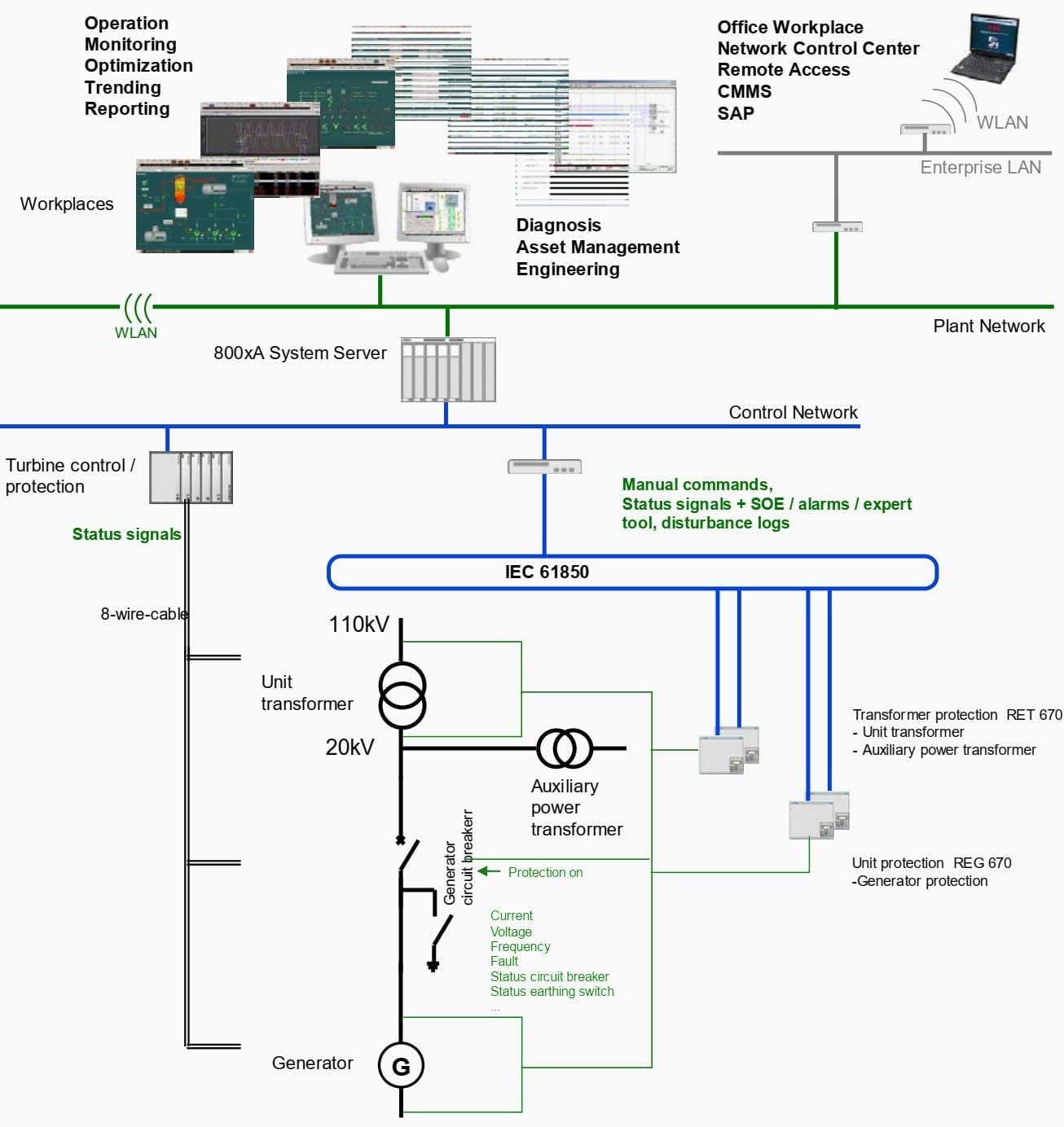
Figure 7 shows the integration of the unit protection to System 800xA. The protection systems consist of two autonomous channels. Ethernet-based IEC 61850 links connect the IEDs to the 800xA control network and the System 800xA server.
A routing device separates the System 800xA control network and the IEC 61850 station bus for save operation.
Figure 7 – RET 670 and REG 670 integration to ABB’s System 800xA

1.3 Fuel storage requirements
When designing fuel storage tanks, it is important to consider the annual consumption, fuel source, and plant locations to determine the appropriate total capacity. For remote areas with challenging access, it is advisable to have a surplus of fuel capacity for at least three months during the seasonal turnaround.
Large gensets produce approximately 5 kWh of electricity per kilogram of fuel. When estimating fuel consumption for different loads, it is important to consider the true reading of consumption, which includes auxiliary usage. In this case, a figure of 3.5 kWh generated per kilogram of fuel should be used.
Industrial plants that have their own in-house generation with multiple units do not require specific standby unit(s). It is highly improbable that all the operating units will experience failure or trip simultaneously. All units need to have the capability to start independently, either through a DC battery or battery-operated air compressors.
This operating condition is relevant to standby units in large industrial or power plants.
Typically, diesel gensets operate with an efficiency of 42% at full load and around 37% at half load, without taking into account the auxiliary plant load. Utilizing waste heat from the engines, the overall efficiency can reach up to 80% during the winter months.
During the summer months, it may be necessary to release a small amount of excess heat into the atmosphere.
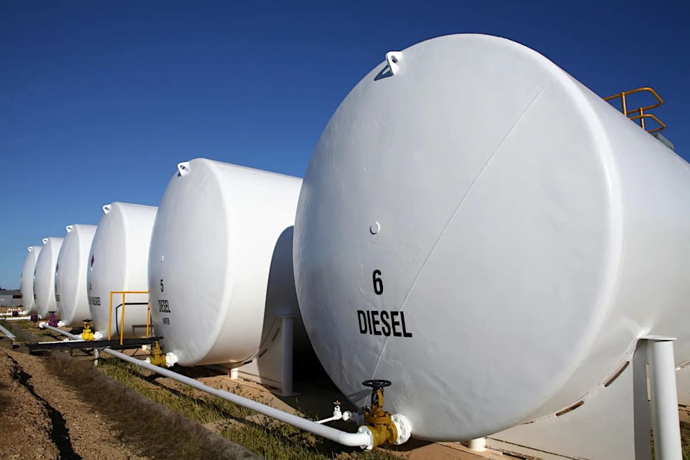
Figure 8 – Diesel fuel storage tanks

1.4 Day tank
The fuel tank designed to provide a day’s worth of fuel is situated either inside or in close proximity to the engine plant. This tank does not need any explosion-proof design or special fire protection installation.
1.5 Fuel stack
Every engine is equipped with a 30 m stack. Avoid combining stacks for multiple units into a single stack. It hampers the efficiency of the unit by causing an increase in back pressure within the stack. Engines with different stroke configurations: A two-stroke engine offers a more affordable, compact, and straightforward design. It generates increased power at the same speed and piston displacement due to the elimination of two idle strokes.
Four-stroke engines offer greater efficiency, reduced noise levels, simplified cooling systems, and enhanced waste heat utilization.
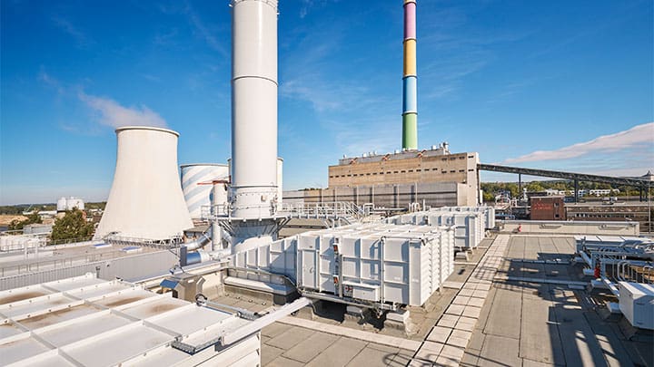
Figure 9 – Fuel stack in power plant

1.6 Supercharging vs. turbocharging
Both superchargers and turbochargers serve as power boosters. Increasing the forced air charge to improve fuel economy can be achieved by either lowering the air temperature or raising air density or pressure, which is considered more effective and preferable. Both forms of forced air induction into the engine cylinders can be utilized effectively.
It is possible to use both on the same diesel engine, but it is not very common.
Superchargers utilize belt-driven compressors connected to the engine crankshaft to increase the amount of air entering the engine’s combustion chamber, resulting in a significant power increase. With enhanced airflow to the engine, the combustion of fuel can be maximized, resulting in a potential power increase of approximately 40-50%.
In a similar fashion, turbochargers utilize the heat from exhaust gas to power turbine/compressors, which in turn injects a greater amount of air into the engines.
The primary function of the turbocharger is to efficiently intake, compress, and deliver air to its required destination. One of the advantages of a turbocharger is its ability to utilize what would otherwise be considered waste. Without a turbocharger, approximately 30% of the fuel’s potential energy is wasted as exhaust gas after combustion.
That’s why it is highly logical to utilize this gas for turbocharging.
Figure 10 – Turbocharger elements
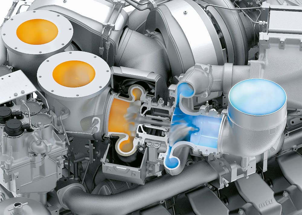

The primary elements of a turbocharger consist of the turbine and the impeller. They are positioned on opposite ends of a shared shaft. The turbine is powered by the thermal and kinetic energy of the exhaust from the engine.
On the other side of the turbocharger, the aerodynamically designed blades of the impeller pull in air and push it with pressure through the intercooler and into the cylinders.
1.7 After cooling
This cooling device is commonly employed in turbocharged and internal combustion engines to enhance their volumetric efficiency by boosting the density of the intake air-charge through isochronic cooling. Lowering the air intake temperature results in a more concentrated intake charge for the engine, enabling a greater amount of air and fuel to be burned during each engine cycle.
This ultimately boosts the engine’s performance.
Turbocharging plays a crucial role in the overall engine design concept. It greatly influences the engine’s performance, impacting its efficiency, power, and emissions.
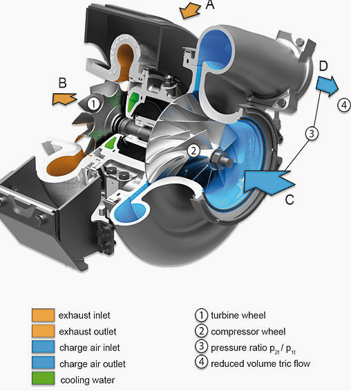
Figure 11 – Turbocharger cross-section where you can see cooling water

2. Black start
As soon as the power goes out and all operations cease, a diesel backup generator will be activated to make the plant ready for a fresh start. The diesel engine will start when there is a sustained (three seconds) loss of voltage logic.
The diesel engine needs to be self-energizing using its own 24 VDC battery. It’s clear that the diesel standby generator won’t need to power the entire industrial plant. It should, however, be able to restart the necessary loads, charge DC batteries, offer lighting, heating, and aid in crucial chemical processes that could be compromised if left in its inactive state for an extended period of time.
The plant will be equipped with station batteries and UPS to ensure that the plant’s critical circuit breakers and other control systems are always prepared to reclose immediately after the main power is restored. The UPS and the station battery need to have enough capacity to operate the control system for a duration of four to eight hours.
When it comes to a power plant, the criteria are slightly different. When the grid is disrupted by unforeseen failures or severe weather conditions, the black start becomes a crucial power plant application. It helps restore functionality to the grid by connecting the nonfunctional islands.
Once it is connected to the grid, it can independently power its own load, eliminating the need for a standby generator. A 1 MW diesel generator is more than capable of handling that load and effortlessly starting the largest motors in the plant.
It is important to ensure that the standby diesel engine has a MW capacity that is at least 1.5 times the rating of the largest pump motor. Additionally, it should have enough capacity to power all the auxiliaries for several hours.
When the standby generator activates, it becomes necessary to readjust and reinstate the power plant auxiliary power distribution system. The bus incoming breakers need to be closed in a specific sequence as instructed by the plant control system. All the necessary plant breakers, including the plant control system, are controlled by DC power from the station battery.
It enables the necessary auxiliary systems to be restarted and assists the generating unit in synchronizing with the grid to provide power to its customers.
Watch Video – Black Start Synchronization
Typically, power plants supply the grid through HV switchyards, where each generator is connected to double busbars. The objective is to gradually incorporate each power plant back into the operational system of the region, thereby reestablishing the overall grid. After the initial generating unit is powered up, it is synchronized with the adjacent switchyard dead bus.
This can be a standalone bus or a bus connected to a nearby power plant. The synchronization is achieved through a process known as “line charging”.
In this procedure, the generator breaker is closed on a bus that is not energized, and then the voltage is gradually increased to reach the generator’s specified value using the GSUT.
Throughout this process, the governor transitions from droop to Isochronuous mode (ISO) with a 0% droop. With this mode, the generator can quickly increase its frequency and voltage to easily synchronize with a remote bus. This adjustment is being made from a remote source to align the speed/voltage with the requirements of the remote source.
When the generator load reaches 10% of its nominal MW rating, the governor switches to the generator droop 2–4% mode to ensure proper load sharing.
Good Reading – The essentials of standby power systems you SHOULD install before the blackout happens
The essentials of standby power systems you SHOULD install before the blackout happens
3. BONUS (PDF): Power Plant Engineering Book
Download Power Plant Engineering Book (for premium members only):
Sources:
- Practical Power Plant Engineering by Z. Bedalov
- Future power plant control – Integrating process & substation automation into one system by ABB






Pease kindly can send us latest news of power plant in detailers