
Estimated Study Time: 22 minutes
Power system redundancy
Nowadays, power system reliability is more important than ever. Regardless of how reliable the individual power-system components may be, some sort of power-system redundancy is necessary to attain high levels of power-system reliability, with the ultimate aim being 24 hour/day availability, 365 days a year. Redundancy offers flexibility in power distribution if it is implemented effectively.
 Key points on how to design fault-tolerant and reliable facility power system
It’s important to note that when more than one path is available for power to flow to the load, the essential components of a system can be moved from one device or branch to another as needed for load balancing, system upgrades or modifications, or equipment failure isolation. Redundancy offers some fault tolerance as well.
Generally, fault tolerance can be divided into three basic categories:
- Fast recovery from failures,
- Protection against “slow-developed” power system failures, where there is enough warning of the condition to allow intervention, and
- Protection against “rapid-developed” power system failures, where no warning of the power failure is given.
The advantages and rising costs and benefits must be compared, as is the case with many corrective and preventative actions.
On the other side, when many UPS modules fail, continuous paralleling of the two UPS systems can be utilized to combine them into a single redundant UPS system from two non-redundant ones (because of failures or maintenance).
Figure 1 illustrates one such implementation. Of particular interest is the ability to parallel UPS systems as required by operational conditions
Figure 1 – Power-distribution system featuring redundancy and high reliability
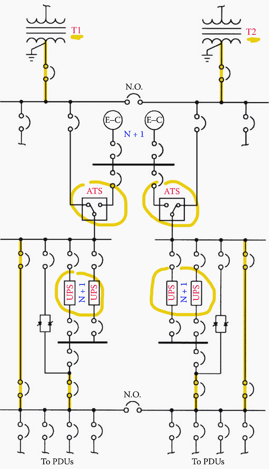
Now let’s break down the power-distribution system shown above and explain what is needed to achieve redundancy and high reliability.
1. How to Design a Critical System Bus
When there is a power outage, many facilities do not need to run every piece of machinery. Key components of equipment can be safeguarded with small, specialized, uninterruptible power systems as opposed to use one big standby power system. For computers and other devices, there are small UPS units with integrated battery supplies available.
Establishing a critical load bus that is connected to a UPS system or generator via an automatic transfer switch (ATS) may be an option if the cost of installing a system-wide standby power supply (using generator or solid-state UPS technology) is prohibitive. In order to keep the protected systems operational, key loads are supplied AC through this separate power supply.
The concept is illustrated in Figure 2. The UPS device supplies electricity to all the equipment required to keep everything running in the case of a power outage.
In most equipment instruction manuals, you can find average power usage numbers. A wattmeter can be used to measure the data if it is not published or provided by the manufacturer.
Figure 2 – An application of the critical-load power bus concept

Make sure to precisely determine which loads are crucial and which can be dropped in the event of a commercial power outage while planning a critical load bus. A large data processing center’s computer equipment will soon reach temperatures where system components may be destroyed or the hardware will shut down automatically if the air conditioning is interrupted while it is still operating.
It might not be required to demand that heat-exchange pumps, chillers, and cooling fans operate continuously. Any downtime, though, should be no longer than one to two minutes. Computer systems that use air cooling can often withstand a cooling interruption for 5 to 10 minutes.
Suggested Course – ETAP Power System Design and Analysis Course
ETAP Power System Design and Analysis Course For Solving Various Practical Problems
1.1 What Power Distribution Options Do We Have
There are essentially twelve building blocks that form what can be described as an assured, reliable, clean power source for computer systems, peripherals, and other critical loads. They are:
- Utility and service entry (step-down transformer, main disconnect, and panelboard, switchboard, or switchgear)
- Lightning protection
- Power bus
- Facility power distribution
- Grounding (check the course at EEP Academy)
- Power conditioning equipment
- Critical load air-conditioning
- Frequency converter (if required)
- Batteries for DC backup power (check the course at EEP Academy)
- Emergency engine-generator
- Critical load power-distribution network
- Emergency readiness planning
If any of these components are not functioning as planned at all times, including during emergencies, a power system supporting a critical load cannot be claimed to be reliable.
Proper training, and periodic reinforcing, is an essential component of a reliable system.
Go back to the Contents Table ↑
1.2 How to Configure the Facility Plant
There are countless hardware setups that can offer redundancy and dependability for a crucial load. Since every circumstance is different, it is necessary to evaluate the options and, more importantly, the risks on an individual basis. The laws of economics demand that cost is always a consideration.
Through proper design, however, the expense usually can be held within an acceptable range.
Design for reliability begins at the utility service entrance. The common arrangement shown in Figure 3 is vulnerable to interruptions from faults at the transformer and associated switching devices in the circuit. Furthermore, service entrance maintenance would require a plant shutdown.
Figure 3 – Simplified service entrance system
In Figure 4, redundancy has been added to guard against the loss of power in the event that one of the connected devices fails. Because the two transformers are situated in different physical enclosures, maintenance can be carried out on one leg without interrupting electricity to the building.
The strategy used to distribute power inside a facility in order to achieve optimal reliability is equally crucial. When working with a campus-style facility or a process or manufacturing plant, this task is more challenging since the important loads may be dispersed across the complex rather than being concentrated in a single room or level.
Figure 4 – Fault-tolerant service entrance system
Figure 5 illustrates power distribution through the facility using a simple radial system. An incoming line supplies the main and line feeders via a service entrance transformer. This system is suitable for a single building or a small process plant.
It is simple, reliable, and lowest in cost. However, such a system must be shut down for routine maintenance, and it is vulnerable to single-point failure.
Figure 5 – Secondary plant distribution using a simple radial configuration
Figure 6 illustrates a distributed and redundant power-distribution system that permits transferring loads as required to patch around a fault condition. This configuration also allows portions of the system to be de-energized for maintenance or upgrades without dropping the entire facility.
Note the loop arrangement and associated switches that permit optimum flexibility during normal and fault operating conditions.
Figure 6 – A redundant, fault-tolerant secondary plant distribution system
Go back to the Contents Table ↑
2. Key Facility Maintenance Steps
Maintenance of the facility electrical system is a key part of any serious energy-management effort. Perform the following steps on a regular basis:
Step #1 – Measure the current drawn on distribution cables. Document the measurements so that a history of power demand can be compiled.
Step #2 – Check terminal and splice connections to make sure they are tight.
Step #3 – Check power-system cables for excessive heating.
Step #4 – Check cables for insulation problems.
Step #5 – Clean switchboard and circuit-breaker panels.
Step #6 – Measure the phase-to-phase load balance at the utility service entrance. Load imbalance can result in inefficient use of AC power.
Step #7 – Measure and chart the power factor of the load. Develop and post a simplified one-line schematic of the entire power network as well as other building systems, including heating, air-conditioning, security, and alarm functions. A mimic board is helpful in this process.
Construct the mimic board control panel so that it depicts the entire AC power-distribution system.
Environmental control systems should be monitored closely. Air-conditioning, heating, and ventilation systems often represent a significant portion of the power load of a facility. Computer-based datalogging equipment with process control capability can be of considerable help in monitoring the condition of the equipment.
The logger can be programmed to record all pertinent values periodically and to report abnormal conditions.
Suggested Reading – My worst experience in the maintenance & supervision of substations
My worst experience in the maintenance and supervision of medium voltage substations
Go back to the Contents Table ↑
2.1 Switchgear Maintenance: Dos and Don’ts
The installation of AC power switchgear at a facility is all too frequently forgotten about until a problem arises. Careless handling of the switchgear’s routine inspection and cleaning has led to a number of failures, including destructive fires. Any switchgear assembly that has arcing involving the main power bus is seriously flawed.
Protective devices may fail to open, or open only after a considerable delay. The arcing damage to busbars and enclosures can be significant. Fire often ensues, compounding the damage.
Moisture, combined with dust and dirt, is the greatest deteriorating factor insofar as insulation is concerned. Dust or moisture are thought to account for as much as half of switchgear failures. Initial leakage paths across the surface of bus supports result in flashover and sustained arcing.
Contact overheating is another common cause of switchgear failure. Improper circuit-breaker installation or loose connections can result in localized overheating and arcing.
It has been observed that most faults in three-phase systems involve all phases. The initial fault that triggers the event may involve only one phase, but because of the traveling nature of an arc, damage quickly spreads to the other lines.
Preventing switchgear failure is a complicated discipline, but consider the following general guidelines:
Guideline #1 – Install insulated busbars for both medium-voltage and low-voltage switchgear. Each phase of the bus and all connections should be enclosed completely by insulation with electrical, mechanical, thermal, and flame-retardant characteristics suitable for the application.
Guideline #2 – Establish a comprehensive preventive maintenance program for the facility. Keep all switchboard hardware clean from dust and dirt. Periodically check connection points for physical integrity.
Guideline #3 – Maintain control over environmental conditions.
Guideline #4 – Accurately select overcurrent trip settings, and check them on a regular basis. Adjust the trip points of protection devices to be as low as possible, consistent with reliable operation.
Guideline #5 – Divide switchgear into compartments that isolate different circuit elements. Consider adding vertical barriers to bus compartments to prevent the spread of arcing and fire.
Guideline #6 – Install ground-fault protection devices at appropriate points in the power-distribution system.
Guideline #7 – Adhere to all applicable building codes.
Suggested Reading – Secrets and warnings in operation and maintenance of GIS substation
Secrets and warnings in operation and maintenance of a Gas Insulated Substation (GIS)
Go back to the Contents Table ↑
2.2 Ground-System Maintenance: Dos and Don’ts
Out of sight, out of mind does not — or, at least, should not — apply to a facility ground system. Grounding is a crucial element in achieving reliable operation of electronic equipment. If a ground system has been buried for 10 years or more, it is due for an inspection. Soil conditions vary widely, but few areas have soil that permits a radial- or screen-based ground system to last much more than 15 years.
The method of construction and bonding of the ground network also can play a significant role in the ultimate life expectancy of the system. For example, ground conductors secured only by mechanical means (screws and bolts, crimping, and rivets) can quickly break down when exposed to even mild soil conditions.
Unless silver-soldered or bonded using an exothermic method, such connections soon will be useless for all practical purposes.
It will not, however, identify breaks in the system. Portions of the ground system still will need to be uncovered to complete the inspection. Accurate documentation of the placement of ground-system components will aid the inspection effort greatly.
Suggested Reading – Practical steps in the design of a substation grounding
Pay close attention to any hidden mechanical connections. Bolts that have been buried for a long time may have suffered severe deterioration. Carefully remove several bolts, and inspect their condition. If a bolt is severely oxidized, it may twist off as it is removed. After uncovering representative portions of the ground system, document the condition of the ground through notes and photographs.
These will serve as a reference point for future observation.
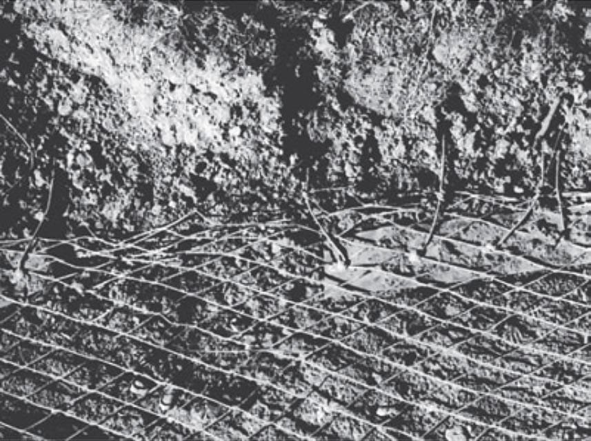
The photos in Figures 7, 8, and 9 illustrate some of the problems that can occur with an aging ground system. Note that many of the problems experienced with the system shown in the photographs resulted from improper installation of components in the first place.
Figure 7 – Ground system inspection #1
Even though a buried copper strap may appear undamaged, give it a pull to be sure. This strap came apart with little effort.

Figure 8 – Ground system inspection #2
Acidic soil conditions created holes in this ground screen.

Figure 9 – Ground system inspection #3
Small pieces of copper strap were used in this ground system to attach radials to the ground screen around the base of a tower. Proper installation procedures would have incorporated a solid piece of strap around the perimeter of the screen for such connections.
Go back to the Contents Table ↑
Source: AC Power Systems Handbook by Jerry C. Whitaker
Related electrical guides & articles


Edvard Csanyi
Hi, I'm an electrical engineer, programmer and founder of EEP - Electrical Engineering Portal. I worked twelve years at Schneider Electric in the position of technical support for low- and medium-voltage projects and the design of busbar trunking systems.I'm highly specialized in the design of LV/MV switchgear and low-voltage, high-power busbar trunking (<6300A) in substations, commercial buildings and industry facilities. I'm also a professional in AutoCAD programming.
Profile: Edvard Csanyi

I am in the Building Mechanical and electrical trade i have been n this industry for over 40 years . since 2010 i have been following your website which i find provides excellent concise and extremely relevant information on the electrical engineering for industry practice engineers.
Thanks for services it’s more helpful.