
Estimated Study Time: 14 minutes
Human machine interface (HMI)
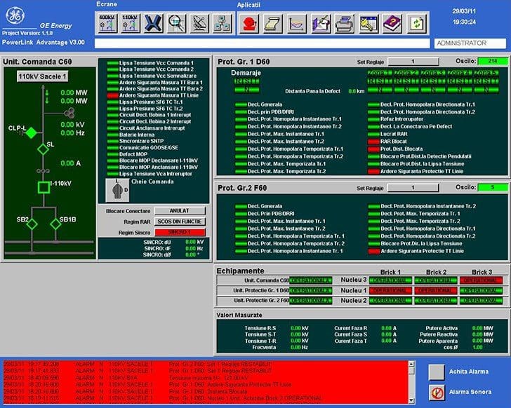
With the introduction of IEDs (Intelligent Electronic Devices), the traditional switchboard interface is being replaced by Human Machine Interface (HMI) software loaded on computer hardware. The designer has a wide choice of HMI vendors that support a wide range of functionality.
 Insulation resistance tests performed on protection relays (photo credit: canahighvoltage.ca)
HMI software may be tightly integrated into a hardware platform such that when the HMI is ordered the software is actually an option for the hardware.
HMI substation designer should use this technical article to determine some of the important criteria for both the hardware and software components of an HMI that should be specified for the system.
1. HMI Hardware
The HMI hardware performs in a substation environment. The most common issue that should be addressed is whether a commercial personal computer, industrial computer, substation hardened computer, or server is required.
The choice of any hardware that does not meet IEEE Std 1613 requires that the designer provide additional system design requirements for at least the following three items:
- Isolation of the computer from the substation battery and AC systems by using an inverter or other device that meets IEEE Std 1613.
- Isolation of the communication ports from interference generated in the substation environment by using fiber optic transceivers or other intermediate device that meets IEEE Std 1613.
- Installation of heating and cooling systems that are remotely monitored and alarmed such that temperatures beyond the computer rating are remotely indicated.
As an option, the designer may determine that the HMI is a “throw away” component providing non-critical functionality that is designed so that it can be “easily” replaced when failure occurs. This approach should not be considered without the designer completely understanding the HMI functionality and replacement procedures.
Depending upon the system architecture, the HMI may have other requirements, including but not limited to the following: multiple serial ports, multiple network ports, an IRIG-B port for time synchronization, mounting requirements (rack mount, panel mount, shelf mount, etc), keyboard, mouse, and redundancy.
Modern HMI often include mobile and tablet versions, rather than only desktop.
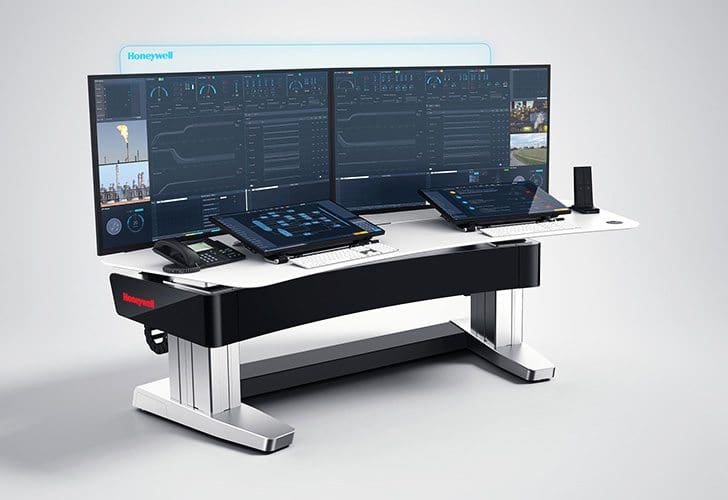
The computer display device should also be carefully selected with respect to temperature and power supply requirements. Other display specifications typically include requirements for size, mounting, and touch screen.
Go back to HMI design criteria ↑
2. HMI Software
HMI software can be divided into the following three categories:
- Operating system software
- Application software that includes any application loaded on the computer
- Configuration file(s) for the settings, displays, and database of the HMI application
Note that the HMI computer may have other applications that also have configuration files, but the specification of these applications and files are not included in this standard.
The HMI application typically runs on computers requiring the latest version of Windows, Linux, or some other operating system. Design tradeoffs can occur when certain requirements are made. For example, the designer may require a certain operating system to meet a corporate standard, which may limit HMI selection.
Go back to HMI design criteria ↑
3. HMI screens
The HMI application provides a series of screens or windows for the monitoring and control of substation devices. The designer should specify either all, part, or additional minimum requirements for these windows that include at least the following:
Requirement #1
A menu system that provides an easy mechanism to move between different windows with no more than three movements such as mouse clicks. This may include a main menu window where all or most windows can be accessed plus a menu bar on each window that provides access to other windows.
I’ve seen few pretty ugly HMI designs so far, and I know that substation engineers always find it hard to get used to it.
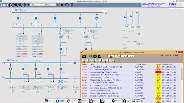
Requirement #2
Alarm annunciator that displays real-time alarms that can be sorted, filtered, individually disabled or enabled, and silenced based upon multiple criteria such as alarm name, group, and time.
Requirement #3
Substation electrical one-line that overlays a summary of the status and analog points over a representation of the one-line. Control should be possible from the one-line window and easily disabled, if desired. Once disabled, however, the enabling scheme used shall meet any security requirements.
The window should display at least the following:
- A geographical orientation of physical equipment including the location of manually or electrically operated disconnect and bypass switches, CTs, PTs, breakers, capacitor banks, reactors, and transformers
- Status and analog data
- Control of devices (if required)
- Tags (if required)
- Colored values/graphics to indicate energized/de-energized status
- Voltage levels
Requirement #4
Protection one-line that is usually a simplified electrical single line diagram. The various protection zones (distance or overcurrent protection, bus and transformer differential protection, transfer-trip schemes, etc.) are indicated. Current and potential transformer connections are shown.
Some protection diagrams include supplementary notes that outline the requirements for taking equipment and protective relays out of service.
Requirement #5
Communication one-line that overlay a summary of the status and analog points related to substation communications over a representation of all system communication connections.
Basic communications statistics should be shown, including:
- Communication status,
- Number of successful and unsuccessful poll attempts and control attempts on the device level,
- LAN statistics, and
- LAN performance,
- etc.
Requirement #6
Trending windows that show present and historical analog values (and/or status values) and can be configured by the user to add/delete analog points, change pen colors, and trending start and stop times. A method should be provided that allows this data to be automatically transferred to a central repository, should one be available.
Requirement #7
Historical alarm display that functions similar to the alarm annunciator window. A method should be provided that allows this data to be automatically transferred to a central repository, should one be available.
Requirement #8
Substation logging functionality that allows operators to leave notes.
Graphics and text shall be large enough and colored to be seen from an ergonomic distance and such that selectable items can be selected via a touch screen or by mouse. The color choices should also be specified by the designer.
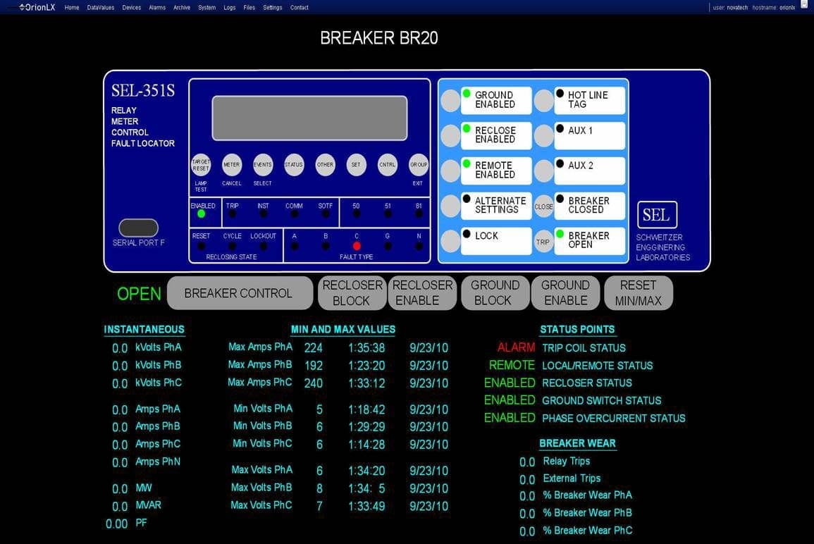
4. HMI control capabilities
The HMI application includes the capability of controlling equipment. The designer shall specify if HMI control is required.
When control capabilities are required, they may include a combination of at least the following:
- Keys and switches (alphanumeric or function, or both)
- Cursor (mouse, trackball, or key controlled).
- Poke points (defined display control selection points)
- Pull-down or pop-up menus
- Physical switches, meters, lights, etc.
The first step is to select the field device.
A visual confirmation on the HMI is presented that gives a clear indication as to what device has been selected in the system database. The operator should also be presented with the options for the selected device (OPEN/CLOSE, TRIP/CLOSE, RAISE/LOWER, START/STOP, ON/OFF, SET POINT VALUE, etc) as well as the ability to CANCEL the control action.
Execution of the desired control action or cancellation option will complete the HMI dialog.
It is not required that this action implement full select before operate functionality down to the control device. An appropriate alternative is to prevent the control operation from occurring if the end device is not available to perform the control (polling has stopped, the device is off-line, the device is being tested, etc).
The designer should include tagging requirements, including how many tag types (information, control inhibit, etc), what additional information is required (comments and how many characters), whether the tagging is replicated in the SCADA master, etc. Placing a tag on a device may also be accomplished by inhibiting a control from occurring by monitoring one or more local/remote switches and possibly even controlling the switch from remote to local.
HMI control actions should be logged in order to uniquely determine who performed the control from the HMI.
Go back to HMI design criteria ↑
5. Other features of HMI
The HMI application will typically provide other features that include report generation from any historical or real-time measurement or status point, log files, links to documentation, help files that are context sensitive, multiple users, multiple security levels, symbol templates, symbol libraries, multiple protocol support, printing, etc.
These applications may or may not be directly linked in the HMI application.
The designer should also consider whether the actual configuration files should have backup files located on the substation computer or if the files should be stored elsewhere. Due to availability, security, and redundancy, this determination may not be trivial and should engage all of the impacted parties.
Go back to HMI design criteria ↑
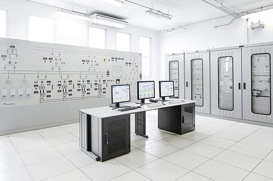
How HMI used to be…
User interfaces at power substations first started out as a switchboard interface long time ago. This was an assemblage of instruments, indicators, annunciators, switches and associated hardware placed on the relay panels or switchboard in such a way as to represent the electrical connectivity and operating condition of the substation.
These devices were connected directly to control and monitoring circuits of power equipment. The operation of equipment through this interface was generally restricted to operators or their delegate.
However, the time has made this switchboard interface old and not usable any more…
Go back to HMI design criteria ↑
References //
- IEEE Standard for SCADA and Automation Systems – IEEE Std C37.1TM-2007 (Purchase from IEEE)
- Supervisory Control and Data Acquisition (SCADA) Systems – National Communications System
Related electrical guides & articles


Edvard Csanyi
Hi, I'm an electrical engineer, programmer and founder of EEP - Electrical Engineering Portal. I worked twelve years at Schneider Electric in the position of technical support for low- and medium-voltage projects and the design of busbar trunking systems.I'm highly specialized in the design of LV/MV switchgear and low-voltage, high-power busbar trunking (<6300A) in substations, commercial buildings and industry facilities. I'm also a professional in AutoCAD programming.
Profile: Edvard Csanyi

Like!! Thank you for publishing this awesome article.
Very good Article, but can you please explain about password management and control Authority provided to operator and engineers.
And one more query is that required 2 system i.e 1. OWS (Operator work Station) & 2. EWS (Engineering work Station) in substation control room to monitor and configuration the system.
Nice article. The IEC is working on a standardized HMI under IEC 61850-6-2, which is effectively an extension of the IEC 61850 standard that includes the graphical elements that are commonly found within Substation and/or Enterprise level HMI applications.
The draft scope of work is:
The International Standard defines the requirements to facilitate the information exchange between IEC 61850 data model and HMI applications within power utility automation systems at the operation, station and field levels (e.g. substation HMI applications, control centre applications, DER management system, configuration and testing tools, etc.).
This International Standard describes the basic principles that need to be considered when building the HMI application, and specify how the HMI’s graphical objects are to be declared in XML using a standardized data model. This International Standard is aligned with the fundamental concepts defined within IEC 61850 and builds upon:
1. The configuration description language defined in IEC 61850-6-1
2. The abstract communication services defined in IEC 61850-7-2
3. The abstract data model defined in IEC 61850-7-3 & IEC 61850-7-4
4. The communication service mappings defined in IEC 61850-8-1
5. The CIM based graphics exchange defined in IEC 61970-453 & IEC 61970-556
This International Standard describes how the common components found within HMI applications are to be described using the HMI Configuration Language, and how they are linked to the data model described within IEC 61850’s System Configuration Language data model. These components may include but are not limited to the single line diagrams; network topologies; toolbars; static/dynamic text; dynamic bus coloring; alarms and annunciations; user dialogue displays; static and dynamic coloring schemes; menus and navigation bars; etc. This covers the display and action functionalities. This International Standard shall provide the required functionalities to automatically generate the HMI application.
For more information, please contact us at http://www.61850university.com. ([email protected])
Great article, just in the moment I am preparing a project, thanks.