
Estimated Study Time: 31 minutes
Busbar protection (BBP)
This technical article discusses criteria and requirements for designing protection systems for busbars in HV/EHV networks. One of the most critical requirements is reliable busbar relay protection to assure power system integrity during fault conditions. This requirement is further emphasized because an incorrect operation of busbar protection will result in quite a mess – the loss of all connected lines, power transformers, and generators, which may lead to a power system blackout.
 Design issues in HV busbar protection systems (substation topology and DC power supply)
Reliable performance of the busbar protection system must be preserved for both In-Zone and Out-of-Zone faults. This is a challenging task since high fault currents may exist at the substation, making it difficult, or even impossible, to avoid saturation of conventional iron-cored CTs.
Most busbar protection systems operate on a differential principle by comparing input and output currents. If a CT saturates, then a false differential current will be derived by the relay.
High-speed busbar protection operation is required since bus faults may result in large fault currents endangering the entire substation due to the high dynamic forces and thermal stresses experienced. For external Out-of-Zone faults (security), the protection scheme must remain stable for all types of fault for the time needed to clear the fault.
Manufacturers use different algorithms to achieve relay stability during CT saturation. While both security and dependability are important requirements for busbar protection, preference is usually given to security.
Four key issues (reliability, operability, maintainability, and cost) need to be addressed when designing a substation and selecting a busbar configuration. At EHV/HV levels, solutions that provide a high degree of reliability can be justified. A modern busbar protection system should dynamically replicate the bus topology.
It should also contain sufficient design flexibility to protect all existing bus arrangements. In general, the main requirements for busbar protection include:
- Security – the probability of an unnecessary protection operation for through faults (Out-of-Zone faults) is low.
- Dependability – the probability that the protection will not operate for a fault on the bus (In-Zone faults) is low.
- Speed – high-speed operation is required to limit equipment damage, and to preserve system transient stability.
- Sensitivity – the ability to detect and clear high resistance faults.
- Selectivity – the ability to isolate only the faulty bus section
All these requirements are interrelated; therefore, it is not possible to satisfy one without affecting the other. The design solution should meet the requirements that correspond to the importance of the substation within the network and the layout of the substation.
1. Substation design issues
The importance of the substation in the network is the most relevant criterion in deciding how complex a BBP system is required. Substation topology is the second most relevant criterion in the design process.
BBP design and its redundancy depend on the substation design and arrangement. For example, for a single busbar substation, the redundancy of the BBP system might be questionable. However, in a breaker-and-half busbar substation redundancy of the BBP system may be a good solution.
At the same time, an unwanted trip will be confined to a single protection zone, and the number of feeders that will be disconnected due to a mal-operation will be reduced. Conversely, if the substation has only one protected zone, the BBP operation will shut down the entire substation.
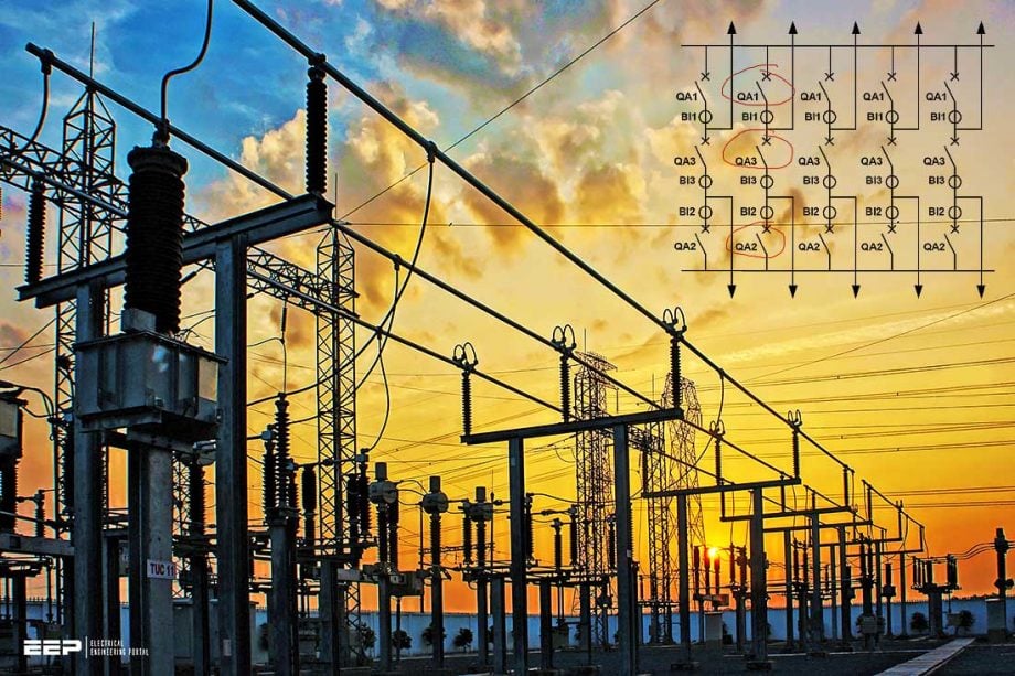
Figure 1 – Symbols used in busbar arrangements

Go back to the Contents Table ↑
1.1 Single busbar
The single busbar arrangement is the simplest substation topology. Substation design from Figure 2 includes a bus section circuit-breaker. However, there are designs where this circuit breaker does not exist, meaning there is only a single busbar. In substations with the bus section circuit-breaker, the BBP considerations can be included in the double busbar with bus coupler arrangement.
In the single busbar arrangement, there is only one protected zone, which is defined by the location of all feeder CTs. Dependability in clearing the busbar faults is ensured by remote backup protection. When a busbar fault occurs, the BBP will trip all circuits connected to the busbar, shutting down the entire substation.
Duplicating BBP will increase dependability and ensure fast fault clearance time if one of the two BBP fails to clear a bus fault.
Figure 2 – Single busbar arrangement
Go back to the Contents Table ↑
1.2 Double busbar single breaker
In substations with a double busbar single breaker with bus coupler arrangement, two BBP zones exist. When the bus coupler is open, busbar faults are directly fed by its connected feeders. During the process of clearing a bus fault, the BBP will open all corresponding circuit breakers and isolate only the affected zone.
The second zone (where fault does not exist) will remain stable since its differential current will stay near zero. If for any reason the BBP fails to operate, the fault will be cleared by remote backup protections, typically Zone 2 distance protections. The number of circuits disconnected will be the same as when the BBP operated properly since the dependability is ensured by backup protections and the selectivity is ensured by the open state of the bus coupler.
This is an example of how the substation arrangement improves the BBP system security and selectivity.
When the bus coupler is closed and the BBP system is active, the isolation between protected zones is achieved by the correct selectivity of the faulted zone and the opening of the corresponding circuit-breakers and bus coupler circuit-breaker. In case of a busbar fault which is not cleared by the BBP, the remote backup protection will clear the fault resulting in the shutdown of the substation and increasing the fault clearance time. Here the duplication of the BBP to increase the dependability and selectivity of the system is a good solution.
Figure 3 – Double busbar arrangements with two sections

When for some reason facilities that will enable the splitting of buses are not available (e.g. BBP out of service, bus coupler bay out for maintenance, no busbar splitting scheme, etc), the substation can be operated with the bus coupler open if there are no other restrictions which prevent such operation (e.g. power flow constraints).
However, during such operating conditions, a busbar fault will shut down the whole substation, and that’s not particularly good.
Operating a double busbar single breaker station in an on-load transfer condition will cause the loss of the entire substation in case of a busbar fault because the BBP will consider the whole station as a single protection zone. When such an operation is unavoidable for a longer period of time, the utility should check the impact on the power system in the event of a busbar fault.
Go back to the Contents Table ↑
1.3 Double busbar with the transfer bus
For the double busbar substation with transfer bus, see Figure 4, there is the possibility of placing a bay in service and connecting it to one of the two busses using the transfer bus. In this situation, the bay is in transfer to its circuit-breaker and uses the bus coupler circuit-breaker to clear faults.
In this topology, the feeder CT location (e.g. internal/external to the transfer disconnector) is relevant to the BBP operation. From the BBP operation point of view, the most interesting location is the external CT, when a bay is in transfer, a third protection zone exists limited by the bus coupler CT and the feeder in transfer CT.
Figure 4 – Double busbar with transfer bus

In the situation of a busbar fault in the busbar connected to the transfer bus, the BBP will clear the fault by opening all connected circuit-breakers including the bus coupler circuit-breaker. In the situation of a busbar fault in the transfer bus, only the bus coupler circuit-breaker will open but the fault will continue to be fed by the transfer bay remote end. In this case, the elimination of the transfer bus fault is achieved by a transfer-trip command to the remote end performed by the BBP or by the remote end Zone 2 protection.
This resemblance to the double busbar with bus coupler arrangement makes all the dependability and security issues true for both arrangements.
Go back to the Contents Table ↑
1.4 Triple busbar
In a triple busbar arrangement, see Figure 5, the application of a BBP follows the same criteria as in the double busbar arrangement substation topology with the peculiarity of having a third busbar and therefore a third protection zone.
By increasing the number of buses the feeders can be more evenly distributed across the three buses and as a consequence, the system selectivity and security are improved. When a busbar fault is cleared or a mal-operation of one BBP zone occurs, fewer feeders are switched out meaning that a larger number of bays can remain in service.
Figure 5 – Triple busbar arrangements
Go back to the Contents Table ↑
1.5 Breaker-and-a-half arrangement
In a breaker-and-a-half substation arrangement, see Figure 6, a BBP trip in one of the busses isolates the respective busbar but does not disconnect any feeder since they will continue to be connected to the other busbar. This is one of the main advantages of this type of substation
the arrangement, meaning that this arrangement has the highest degree of selectivity and security.
In this topology, the BBP has two independent protection zones, each associated with its own busbar. The implementation of this protection is simpler than a double busbar arrangement since there is no CT switching, transfer buses, bus coupler, etc.
The redundancy could result in a reduction in system security, as explained before, but, unlike the other substation arrangements, an unwanted trip will not disconnect any feeder except to isolate the faulted busbar and result in all substation feeders being connected to one single busbar. Therefore, redundancy of the BBP is not followed by a reduction of system security.
As a result, in these substations the use of a second BBP system is justifiable.
Figure 6 – Breaker-and-a-half arrangement
Go back to the Contents Table ↑
1.6 Double busbar with double breakers
For double busbar double breakers substation arrangements, see Figure 7, the considerations are similar to that of the breaker-and-a-half topology.
However, note that it is of utmost importance to utilize the re-trip feature for breaker failure protection when CBF starting for both breakers in one feeder bay is initiated from a single contact or a single protection relay and CBF pickup is set under load current of the feeder.
Figure 7 – Double busbar arrangements with double breakers
Go back to the Contents Table ↑
1.7 Ring busbar
In ring-type substations, see Figure 8, the protection of the busbar is typically not performed by BBP systems as explained in the previous arrangements. Here, each busbar segment is limited by two consecutive circuit-breakers being protected by the corresponding feeder protection that measures the two adjacent CT currents.
Figure 8 – Ring busbar arrangement
Go back to the Contents Table ↑
2. Design issues
2.1 Busbar protection arrangement
2.1.1 Conventional busbar protection arrangement
In the past, before numerical de-centralized busbar protection was available, busbar protections were constructed centrally. All process data, such as CT currents, isolator positions and tripping channels had to be wired back towards the central position of the busbar protection panel.
Considerable interconnection (such as start circuit breaker failure protection, block auto-reclosure, etc.) between the other protection panels had to be made. In those conventional arrangements, many cables had to be used, the engineering, commissioning and maintenance was quite a time consuming and costly.
Figure 9 – Conventional busbar protection arrangement
Where:
- Trip Circuits
- Secondary Currents
- Isolator Positions
- Interconnections
Go back to the Contents Table ↑
2.1.2 Numerical centralized busbar protection arrangement
Numerical centralized busbar protection can be found in new substations as well as where retrofit of old conventional BBP was made and the cables were still in good condition. In a numerical centralized arrangement, the amount of cabling is approximately the same as it was in conventional arrangements.
Furthermore, the numerical technique allows fast and easy connection with substation automation systems which allow fast fault analysis and monitoring.
Figure 10 – Numerical centralized busbar protection arrangement
Where:
- Trip Circuits
- Secondary Currents
- Isolator Positions
- Interconnections
Go back to the Contents Table ↑
2.1.3 Numerical decentralized busbar protection arrangement
In new and refurbished substations, where the cabling is completely new, numerical decentralized busbar protection can often be used today. Bay dedicated protection panels can be built, where the bay units of the de-centralized busbar protection are located close to the bay protection devices.
The bay protection panel designs can be replicated. During engineering, testing, commissioning and maintenance work this concept can save time. Further savings can be made if more integrated functionalities are used if this is acceptable from the overall dependability point of view.
Figure 11 – Numerical decentralized busbar protection arrangement

Where:
- Trip Circuits
- Secondary Currents
- Isolator Positions
- Fibre-optic cables
Go back to the Contents Table ↑
2.2 DC power supply design for busbar protection
The power supply is a very important aspect of busbar protection system design. Its design should take into account the desired dependability and selectivity to adapt to the kind of BBP (e.g. whether if it is centralized or decentralized). In many cases, modern busbar protection devices are equipped with more functions than just busbar protection.
Several situations can arise, where the risk of losing the busbar protection due to DC loss might occur:
- Maintenance of one station battery
- Damage to one station battery
- Weak station battery
- Short circuit of a DC – circuit
- Interruption of a DC – circuit
- Damage to a power supply module within the protection
Go back to the Contents Table ↑
2.2.1 Centralized busbar protection
In the centralized BBP system, the protection relay is concentrated in one location within the substation. It is here that all the substation currents are used to perform the differential function, all switchgear status is applied to give the correct current balance to feed the tripping zone logic, and all the circuit breaker failure circuits are concentrated.
At the same time, all trip circuits to the substation circuit breakers are issued from this location.
The probability of losing the BBP due to power failure can be reduced by using a battery backup system. In this case, the protection system is supplied by two batteries and, an auxiliary relay commutes between batteries in case of a battery failure, Figure 12a).
Figure 12a – BBP central unit power supply using two batteries
To have a BBP out of service due to power failure, both batteries have to fail which is more unlikely to occur, consequently, the need for remote zone 2 operations are reduced. If for the dependability of the system the choice is made to duplicate the BBP, it should be accomplished with the use of two independent batteries, Figure 12b).
If one battery fails, the corresponding BBP will be out of service but the second protection will remain in service.
If a duplicated battery system is unavailable then no duplication of the power supply exists and there is no advantage to having two BBPs in case of a power failure; both BBPs will be switched off and remote Zones 2 will have to operate in case of a busbar fault.
Figure 12b – BBP central unit power supply by separate batteries
Go back to the Contents Table ↑
2.2.2 Decentralized busbar protection
In a decentralized BBP, there are two power supplies that need to be considered: the central unit power supply and the bay unit power supply. The considerations for the power supply of the central unit are similar to the centralized BBP power supply; for example, it can have a backup with a second battery if there is no second BBP.
The bay units, which are located in each bay panel, can be powered from the local panel power supply system. In feeder protection systems, composed of one single main protection, both the bay unit and the feeder protection can share the battery supply by distinguishing power circuits.
It is acceptable to do this if the main protection has no backup function over the BBP, typically reverse distance zone. See Figure 13a.
Figure 13a – Power supply in a bay panel: BBP bay unit and feeder protection sharing the same battery
If the battery fails, loss of the power supply will shut down both the BBP and one of its backup protections, resulting in no advantage of having backup protection in case of a power failure. In this case, both protections should be supplied using separate batteries, Figure 13b).
Figure 13b – Power supply in a bay panel: BBP bay unit and feeder protection powered supplied by separated batteries

In feeder protection systems composed of two main protections, these are normally supplied by separate batteries for reasons of redundancy. In this case, the BBP bay unit can be supplied by one of the batteries without compromising its dependability, Figure 14 below.
Figure 14 – BBP bay unit sharing the same battery with one feeder protection
An alternative to this is to supply each bay unit with the same power supply as the central unit. In this solution, there is a dependency of the bay units and the central unit on the same battery supply.
The consequence of losing one BBP element’s power supply will lead to the loss of all of the BBP systems, Figure 15.
Figure 15 – Decentralized BBP power supply using one battery
To increase the overall availability of the BBP system, the power supply system can be designed in one of the following two ways, as shown in Figures 15 and 16.
Figure 16 – Decentralized BBP power supply using two batteries and an auxiliary relay to commute between batteries
In many cases, modern busbar protection devices are equipped with more functionality than just busbar protection (e.g. circuit breaker failure, end fault, overcurrent backup protection). In order to achieve higher availability of the busbar protection system, redundant power supplies in the central and bay units can be used to increase availability.
Figure 17 – Redundant power supplies within the central & bay units of decentralized BBP

Go back to the Contents Table ↑
Source: Modern Techniques for Protecting Busbars in HV Networks by Cigre Working Group B5.16: Zoran Gajic (SE), André Quaresma dos Santos (PT), Hans-Werner Funk (DE), Kenneth Opskar (NO), Jose Miguel Yarza Narro (ES), Damien THOLOMIER (CA), Ljubomir Kojovic (US), Phil Beaumont (GB), Juergen Westerfeld (CH)
Related electrical guides & articles


Edvard Csanyi
Hi, I'm an electrical engineer, programmer and founder of EEP - Electrical Engineering Portal. I worked twelve years at Schneider Electric in the position of technical support for low- and medium-voltage projects and the design of busbar trunking systems.I'm highly specialized in the design of LV/MV switchgear and low-voltage, high-power busbar trunking (<6300A) in substations, commercial buildings and industry facilities. I'm also a professional in AutoCAD programming.
Profile: Edvard Csanyi

I don’t know if you have obtained Permission from CIGRE to use extracts of their Technical Brochure 431 written by Working Group B5.16 and published in 2010 …
But the full Technical Brochure can be obtained here:
https://e-cigre.org/publication/431-modern-techniques-for-protecting-busbars-in-hv-networks
Note CIGRE Individual Members or staff of CIGRE Collective (corporate/institution) Members can download for free
Thank you very much for this sound educative informations.
Keep it on.
Outstanding explanation, keep it up. Your articles are very much informative. Thanks for sharing it