
Estimated Study Time: 22 minutes
Power grid communications
Communication networks are an integral part of interconnected transmission lines in a power grid, analogous to the spinal cord for control signal and information exchange among substations, data hubs, and load dispatch centers. This article covers the major trend and design aspects of fiber optics communication link in power transmission line network and its interface with automation and protection systems.
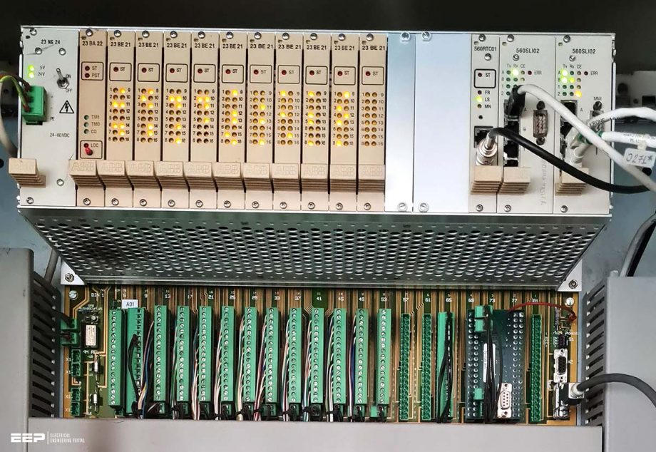 Hints for a good design of an optical communication system for a transmission line network (on photo: Internals of an RTU in a substation; photo credit: Bishal Lamichhane)
When integrating a new substation, generating station, or a transmission line section into a power grid, along with the power flow, the designer must ensure perfect interface and compliance with the existing communication channel.
While the Power Line Carrier Communication (PLCC), Microwave, and radio links were once very prominent in power grids telecommunication, in this article, however, the focus will be on the fiber optics link and terminal equipment in power grid communication.
A sample case of a 132 kV transmission line extension project serves as an occasional reference for communication system design illustration.
1. Design preface
The communication network in the power grid is one of the most interrelated systems that require perfect compliance in equipment and protocol selection. While the high voltage components are relatively unchanged over decades in terms of operating principles, the communication protocols and equipment are seeing astonishing advancements every year.
So, weighing the selection between cost-effective and contemporary standard protocols is the key to making the communication design future-proof and scientific. The figure below is a conceptual diagram of a new section of a 132 kV transmission line and substation extension with the existing 132 kV power grid.
In this case, the major objective would be to design a swift and reliable interface between communication equipment at the rear end of the proposed transmission line and source equipment at the power plant, including the remote load dispatch center.
Figure 1 – Conceptual drawing for a sample project
In most cases, a general scope of Fiber Optic Communication design and installation in a power grid substation would comprise of the following major parts:
- Installation of appropriate multiplexing equipment along with suitable optical line interfaces, tributary cards, drop-insert multiplexers, compatibility adapters, and subscriber line interfacing cards.
- Digital Distribution Frame patch facilities, equipment MDF, and interconnections to the supplied equipment at the defined interfaces.
- System integration of the supplied subsystems and integration with existing communication equipment for seamless transmission through the communication channel.
- Synchronization of new communication equipment with an existing network utilizing the existing clock (if available) or additional clock as required.
- And, most important of all, integration of the supplied system with the user equipment such as RTUs, SAS, IEDs, SCADA system, any available PLCC equipment, etc.
Go back to the Contents Table ↑
2. Prerequisites of system design
2.1 Knowhow of prevailing setup
While the primary objective is always to get the best solution for the lowest price, in the case of extension projects, the design engineers must also keep an eye on the existing setup. The issue of back-compatibility and upgradations should be properly accessed in existing equipment, even more so in the case of proprietary legacy setups.
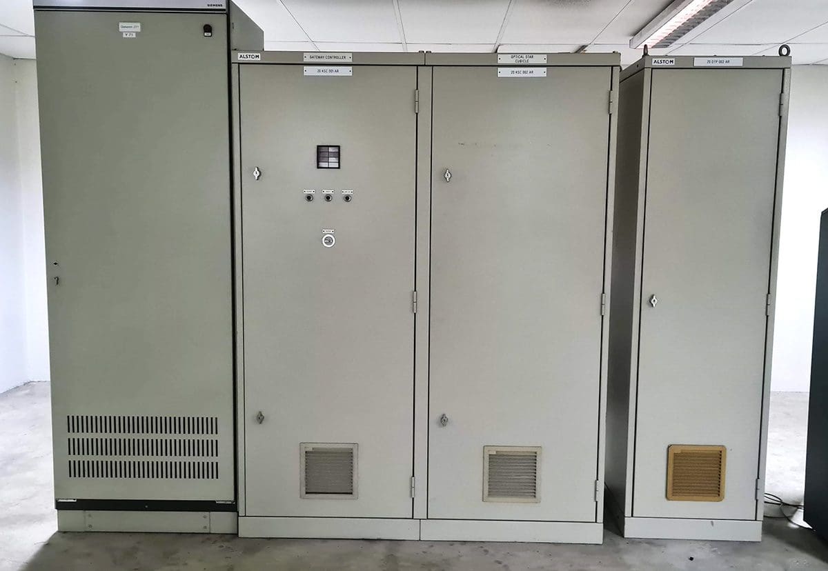
Figure below illustrates one such group of communication equipment in existing substations that might need proper interfacing and compatibility adapters before integrating new equipment.
Figure 2 – Existing gateway controller and optical cubicle in a substation
Go back to the Contents Table ↑
2.2 Understanding the major functions and requirement
2.2.1 Tele-protection function
Teleprotection equipment are vital part of grid substations to transmit and receive remote protection command from distance and differential relay, conveyed via communication medium. Installation of latest communication and interface protocol helps to minimize the transfer time of signals between teleprotection equipment, which enables swift fault clearing in transmission lines.
The offered communication equipment and medium shall support integrated distance and differential teleprotection interface by adding necessary hardware in the same equipment.
Related electrical guides & articles


Bishal Lamichhane
Electrical Engineer (B.E Electrical, M. Sc Engineering) with specialization in energy systems planning. Actively involved in design and supervision of LV/MV substations, power supply augmentations and electrification for utilities and bulk consumers like airports and commercial entities. An enthusiast and scholar of power systems analysis.Profile: Bishal Lamichhane
