
Estimated Study Time: 21 minutes
Switchgear and protection design
The step-down substations make up for more than 80% of total grid substations and are the focal point of sub-transmission and distribution systems. Usually, HV substations within the power transmission grid are assigned with the dual function of switching and stepping down, thus requiring a highly reliable and fast operating substation protection and control mechanism.
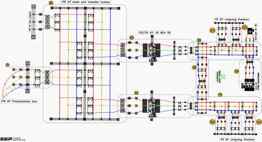 Figure 1 - 132/ 33 kV substation layout and protection zone
This article shall revolve around the design overview of switchgear and protection systems in a typical 132/33 kV power grid substation. There are a lot of design contingencies and constraints that sum up to decide the selection of the right type and number of protection units to ensure reliable and safe power supply/ switching operation.
The illustration of tips and techniques to optimize the protection system design based on those factors shall form the basic core of this article.
1. Protection design overview
1.1 Principle of protection
Substation protection is a streamlined function that includes real-time sensing of abnormality, analyzing it with no time delay, and releasing commands to isolate the faulty section to avoid probable catastrophe. The location of sensing elements and breaking units determines the zone of protection.
Overlapping of protection zones ensures no portion is left unprotected and backup for the primary protection system.
Figure 2 – Substation protection principle
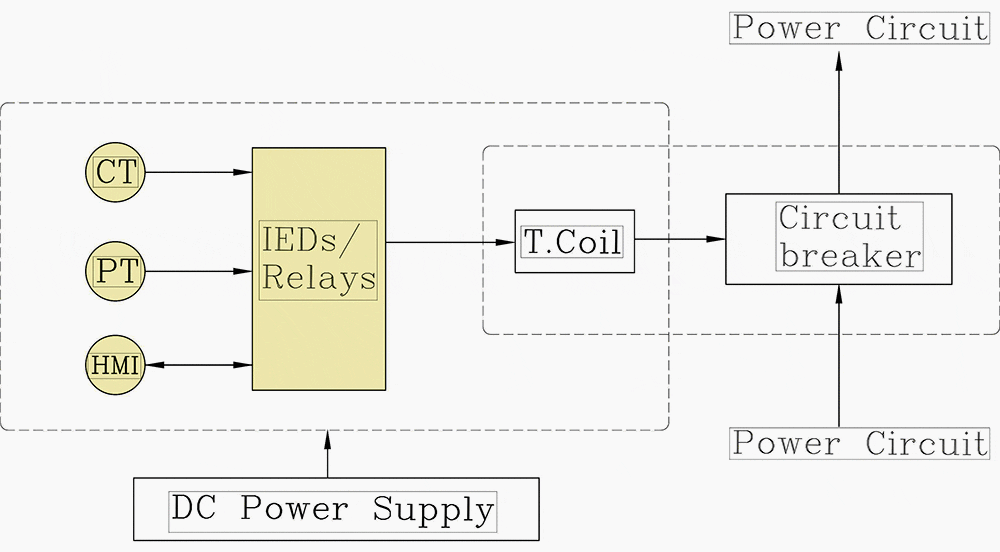
Irrespective of the size and nature of substations, the basic principle of protection remains identical. Sensing elements, relay, and breaking devices form the main core of substation protection and control.
For 132/33 kV substation in Figure 1 (click to zoom), the placement of sensing and circuit breaking components is vital to segregate the protection zone of multiple incoming and outgoing radial feeders, transformer bays, and busbar.
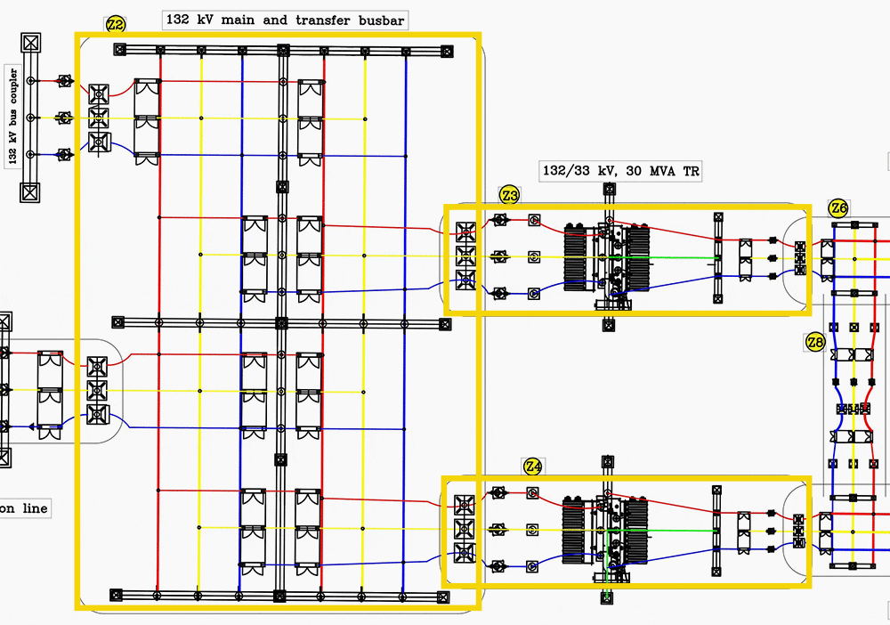
The unit (Z2, Z3 and Z4) and non-unit protection zones are indicated by closed and open boxes, respectively, in Figure 1 above.
Figure 1 (Detail) – The unit (Z2, Z3 and Z4) and non-unit protection zones
1.2 Design case of a typical substation
The basic layout diagram of the substation switchyard shown in Figure 1 illustrates the most common configuration of a typical step-down Air-Insulated substation for sub-transmission and primary distribution in load centers. The ingress and egresses mandatorily require an appropriate protection mechanism to isolate the substation from external disturbances.
But what else needs to be covered to ensure safe and reliable operation? Let’s dig into it a bit.
Related electrical guides & articles


Bishal Lamichhane
Electrical Engineer (B.E Electrical, M. Sc Engineering) with specialization in energy systems planning. Actively involved in design and supervision of LV/MV substations, power supply augmentations and electrification for utilities and bulk consumers like airports and commercial entities. An enthusiast and scholar of power systems analysis.Profile: Bishal Lamichhane
