
Estimated Study Time: 12 minutes
Planning of medium voltage systems
Medium voltage networks are networks with rated voltages of over 1kV and up to 36kV. Medium voltage switchgear is used in transformer substations and switching substations, and in secondary unit substations and customer substations (in public utility networks only). This technical article is exclusively concerned with medium voltage switchgear for transformer substations and switching substations.
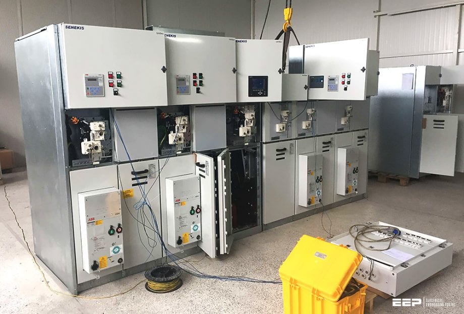 Design tips for medium voltage systems and switchgear in power substations (on photo: Testing the medium voltage switchgear type 'UniSec'; credit: senekis.gr)
On account of the widely differing structures which result from the demands placed upon them, a distinction is made between industrial and power station service networks on the one hand, and public utility networks on the other hand.
For example, the most frequent network voltages in Germany are Public utility networks: 10 kV and 20 kV, and for industrial and power station service networks: 6 kV, 10 kV and 30 kV.
Apart from the high load density, industrial and power station service networks are frequently characterized by:
- High demands for reliability of supply,
- High demands for voltage quality,
- High proportion of motor loads, and
- High short-circuit powers.
As a consequence, the structure of industrial and power station service networks is strongly influenced by the requirements of the relevant production process.
The requirements for configuration and the rated data of the medium voltage switchgear installations are to be deduced individually from the network structure concerned. It is normally essential to perform a network calculation (e.g. with NEPLAN) in order, for example, to take account of the contribution of motor loads to the short-circuit current or to be able to formulate requirements for network protection.

The function of public utility networks is primarily to provide blanket supply of electrical energy while fulfilling the following conditions:
- Appropriate reliability of supply
- Adequate voltage quality
- Cost-effectiveness
As there are no restrictive planning criteria with regard to the appropriate reliability of supply, a number of standard network concepts which provide a level of reliability generally accepted as appropriate have become established in the course of time.
The fundamental functions of network planning and the most important standard network concepts are therefore presented in the following paragraphs.
Planning and optimization of MV networks for public power supply
The function of network planning is nowadays less that of planning the network configuration than rather questioning and optimizing the existing, in many cases historically determined, network structures when replacement investments are impending.
Frequently, the background conditions dictated by the network operator’s supply function no longer correspond to the background conditions against which the medium voltage networks were established and expanded.
Typical changes which can have feedback effects on the network structure and provide occasion for fundamental replanning or target network planning comprise the following:
- Changed supply areas, for instance as a result of corporate mergers,
- New or shifted load centres, with total load nearly stagnating or only rising slightly,
- Inaccurate load forecasts,
- Integration of decentralized generation facilities,
- Increased pressure on costs, increased equipment reliability,
- Improved network management.
Fundamental planning comprises the following aspects and focal points:
- Analysis of the actual situation,
- Definition of planning principles and criteria,
- Load forecast,
- Development of target network variants,
- Technical and commercial comparison of the network varianrs, and
- Definition of the target network.
The target network defines not only the network structure, but also the locations and sizes of transformer substations and switching substations and the requirements for the medium voltage switchgear.
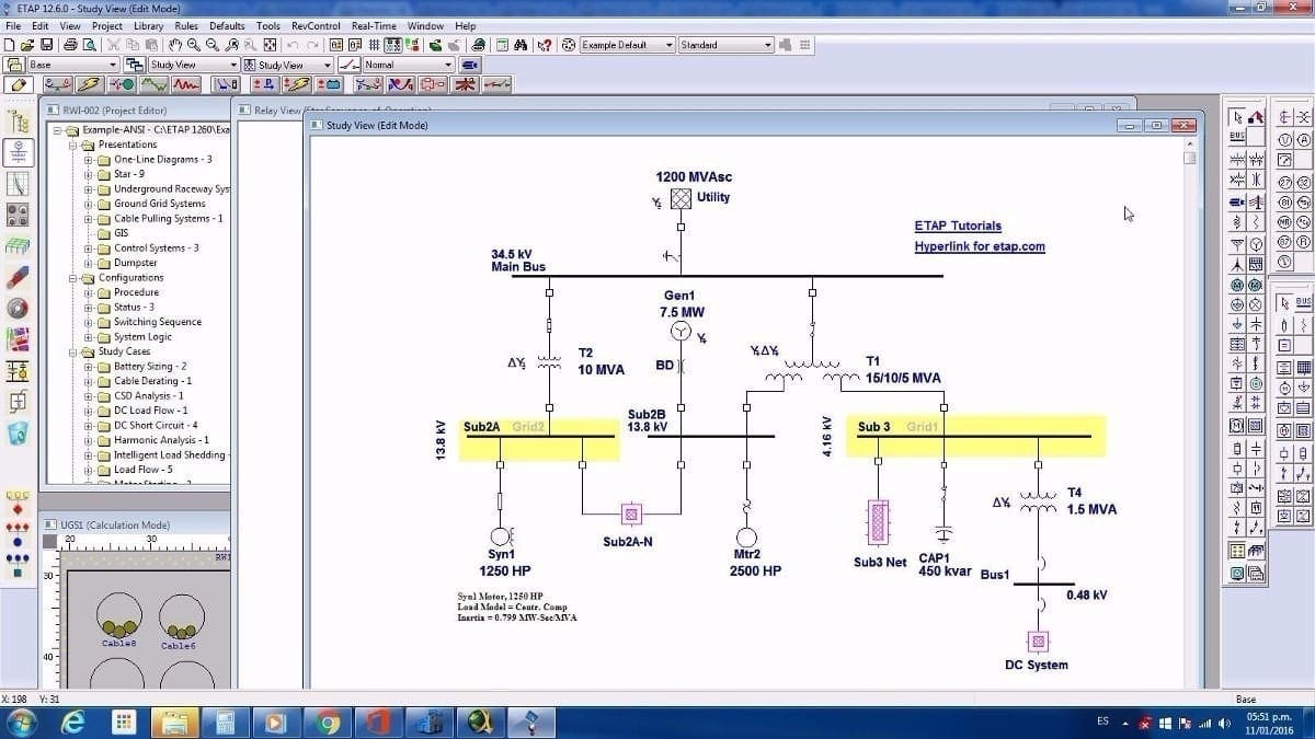
Network calculations (e.g. with ETAP) are performed in the course of analysis of the actual situation and to assess the target network variants. In that process, load flow and phase fault current calculations are accompanied above all by probability calculations to estimate reliability. Probability calculations on reliability facilitate quantification of the reliability of supply in distribution networks.
The influence of different network and system configurations on service reliability can be quantified in this way on the basis of reliability characteristics.
Examples of reliability characteristics include interruption frequency (stated as 1/a), i.e. the expected value for the frequency with which interruptions are to be expected by consumers in the network, and non-availability (stated in min/a), i.e. the probability of finding a consumer without supply. The reliability characteristics than describe the cumulative effects of all failures in the network.
Furthermore, if the costs of interruptions are known, details of the annual costs caused by interruptions to supply can be presented. The results of the reliability calculations for each consumer are as follows:
- Expected interruption frequency (n 1/a)
- Expected non-availability (in min/a)
- Expected average interruption duration (in min or h)
- Expected energy not supplied on time (in MWh/a)
Those for the system as a whole are as follows:
- SAIFI (System Average Interruption Frequency Index): Expected average interruption frequency in 1/a)
- SAIDI (System Average Interruption Duration Index): Expected average non-availability (in min/a)
- Expected energy not supplied on time (in MWh/a)
In addition, the contributions of the individual pieces of equipment to the “unreliability” of the network can be quantified. This allows the importance of the equipment for the function of the network to be determined and, for example, priorities to be deduced for maintenance and replacement work.
It is impossible to say in general which network concept provides the most efficient ratio of network costs to service reliability for which supply job, as the forms of the higher level high voltage networks and the subordinate low voltage networks and, last but not least, the rated system voltage which is usually specified, also have to be taken into account.
For transformer substations in explosion-proof design, there are no medium voltage connections between the substations. In these cases, the simple ring network concept as shown in Figure 3 is usually preferred.

In extensive catchment areas with low load density, it is often more economical to implement a concept with opposite stations as shown in Figure 4. The opposite stations can be designed as switch-disconnector systems.

When load centres for from the transformer substations are to be supplied, it is useful to provide a load centre substation as shown in Figure 5. This is connected to the transformer substation by feed cables and supplies power close to the load, for example via a ring network.
Load centre substations are to be designed as circuit-breaker systems.

Networks in which the transformer substations are connected on the medium voltage side are used when those substations are not in intrinsically safe design. Back-up supply is then effected through the medium voltage network.
The transformer substations are connected together either directly by distribution cables (Figure 6) or by feed cables as in the opposite station concept shown in Figure 7. These network concepts can provide an economical alternative when the construction of an additional transformer substation is to be avoided, or initially implemented with one transformer only.

The cost-effectiveness is however to be checked for the individual case concerned.
Otherwise, for example, high circulating currents could flow or the short-circuit withstand capability of equipment could be exceeded.

In practice, the load density within the supply territory of a distribution network operator frequently varies over quite a large range, and the higher and lower level networks are not uniform.
This means that the network concepts presented are mostly not encountered in their pure for, but as hybrids.
A common feature of all the network concepts presented is the radial operating mode of the distribution cables, which not only facilitates simple operational management (apart from the exception mentioned above) but also a simple protection strategy and troubleshooting, particularly with single phase faults (earth faults / short-circuits to earth).
Sources:
- Pocket book by ABB
- Optimal reconfiguration of radial MV networks with load profiles in the presence of renewable energy based decentralized generation by Nasser G.A. Hemdana, Benjamin Deppec, Magnus Pielke, Michael Kurrat, Tanja Schmedes and Enno Wiebene
Related electrical guides & articles


Edvard Csanyi
Hi, I'm an electrical engineer, programmer and founder of EEP - Electrical Engineering Portal. I worked twelve years at Schneider Electric in the position of technical support for low- and medium-voltage projects and the design of busbar trunking systems.I'm highly specialized in the design of LV/MV switchgear and low-voltage, high-power busbar trunking (<6300A) in substations, commercial buildings and industry facilities. I'm also a professional in AutoCAD programming.
Profile: Edvard Csanyi

Dear Edvard,
I am trying to size the overcurrent protection for the primary of a 2500KVA utility transformer Delta/Wye at 34.5KV., i came up with 41A but the feeder is coming out of a Metalclad switchgear with drawout breakers , I looked into NEC 450-3A stating in the breaker column stating 700% of my transformer FLA .or 41A x 700% for TX with an impedance of 5.75 , please advise
Also the total load on the MetalClad Switchgear is 9375 KVA at 34.5KV or 157A what is the multiplier for the Main and Tie breaker is it 125%? The Metal Clad Switchear is fed by two 34KV lines and a tie breaker .
it seems like those settings for the breakers for the transformers will be higher , even though the 700% is to compensate for the magnetizing current . I am a member , I have been reading your articles for a while , I usually do design for low voltage power systems (up to 600 V) and some 15.5KV using E power fuses. I am learning more about these MV stuffs.
Thanks in advance