
Estimated Study Time: 40 minutes
Substation Design Complexity
It’s always good to emphasize that substations can be a major headache for staff if they’re not designed properly. Because of this, it is essential for the success of a substation’s operation and maintenance to have a well-designed layout, an organized arrangement of busbars, and a set of intelligent interlocks. However, this is often not the case and the substation crew is struggling with switching operations of circuit breakers or switches and have many other protection problems.
 Dos and don'ts in designing substation layout, implementing interlocks, operation and special applications
The construction of new substations and expanding existing facilities are commonplace projects in electric utilities. However, due to its complexity, very few utility employees are familiar with the complete process that allows these projects to be successfully completed.
Substations are the points in the power network where transmission lines and distribution feeders are connected together through circuit breakers or switches via busbars and transformers. This allows for the control of power flows in the network and general switching operations for maintenance purposes. Various factors affect the reliability of an electrical substation or switchyard facility, one of which is the arrangement of switching devices and buses.
The switchyard design process has limiting factors that are to be optimized for best-fit design parameters, such as low capital cost, personnel/equipment safety, reliability of supply, low operating cost, low cost of energy generation, high efficiency, simplicity and reserved capacity for future growth.
This technical article elaborates on the switchyard busbar layout. The switchyard layout engineering is discussed in which the switchyard equipment arrangement is affected by the busbar layout. The design considered factors are presented to see the how that would be impacted by the selected busbar configuration. Then, different switchyard busbar layouts are compared and contrasted.
Finally, from operational view point, the interlocking schemes for single-bus and double-bus arrangements are addressed for safe operation procedure.
- Layout Engineering
- Switchyard Design Consideration
- How to secure supply? Single, double or triple connections?
- Are you planning switchgear extending in the future?
- How easy and safe can switchgear be maintained?
- Is switchgear operation flexible enough?
- Is protection arrangement wisely chosen?
- Short circuit limitation and parallel connections issue
- Matching the land area and the switchgear type
- Cost and how to justify the substation layout design
- Switchyard Layout
- Interlocking Analysis and Protection Philosophy
1. Layout Engineering
Substation layout essentially consists in arranging a number of switchyard components in an orderly pattern governed by their function and rules of spatial separation as described in an electrical single-line diagram. A list of required documents must be fulfilled prior to drafting the switchyard layout, namely, single-line diagram, general layout plan, the orientation of line elevation, and control room building.
The basic drawings include a single-line diagram, general arrangement drawing, electrical plan and section, control room architectural layout, structural layout, grounding layout, civil layout, erection key diagram, lightning layout, and many others.
Some parameters differ based on substation application as per below:
- Nature of bus bars (i.e., rigid or flexible/strung bus)
- Orientation of busbar
- Location of equipment
- Manner of inter-connections
- Structural arrangement
- Direct stroke lightning Protection
Furthermore, the switchyard layout relies on several factors that impact the layout selection. These factors are:
- Reliability
- Ease of construction and provision for extension
- Ease of operation and maintenance
- Safety of operating personnel
- Land requirement
- Safety of Equipment and installation
- Aesthetic look
- Economy
As many think the busbar scheme selection is a rather straightforward decision that is derived from a reliability viewpoint, it is not that simple. Seemingly, the busbar scheme has a profound impact on all of these factors making it a difficult task to finish.
Detailing this task is burdensome, but it is enough to mention that the required reliability measures that are constrained by some economical factors, land requirements, and topological factors would affect the final busbar scheme choice.
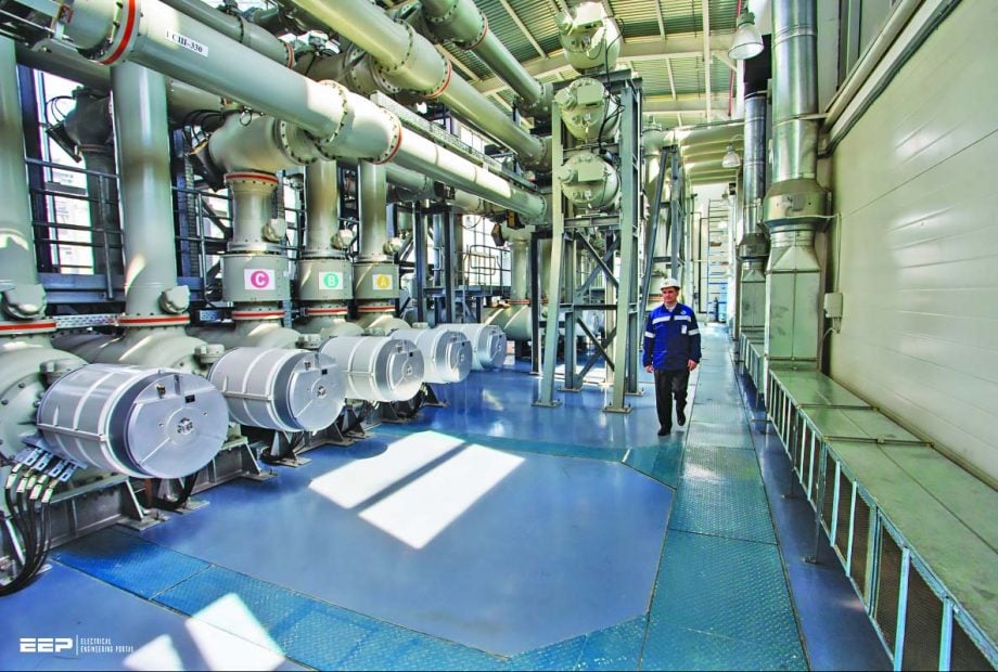
Figure 1 – An example of 33kV and 220kV busbars

Go back to the Contents Table ↑
2. Switchyard Design Consideration
There are factors that are born in mind prior to starting the switchyard design process as elaborated below.
2.1. How to Secure Supply?
Ideally, all substation circuits and equipment would be redundant, allowing for continuous service even after a fault or during maintenance. The price tag for this is sky-high. Therefore, measures have been taken to find a happy medium between supply-side assurance and heavy investment in infrastructure.
It is acknowledged that increasing the level of circuit duplication may weaken supply security by creating more potential points of failure (leakage paths to Earth, for instance).
Therefore, supply-side security may be evaluated in light of the impact of this potential plant loss owing to fault conditions or maintenance interruptions.
Figure 2 – Typical general layout of line feeder supplied via double busbars

Go back to the Contents Table ↑
2.2. Switchgear Extending In the Future?
The substation should be built with expansion in mind. Care must be made to limit the number of outages and their duration when adding switchgear bays to an existing substation.
Due to the disruption caused by making large changes (like switching from a single to double busbar layout) during a later expansion, it is preferable to install the ultimate arrangement from the start. By installing busbar disconnectors in advance (in what are called “skeleton bays” when they are used to accommodate minor alterations like the addition of an overhead line or cable feeder bays), outages can be kept to a minimum.
In contrast, an open terminal switchyard setup gives the customer more options in terms of switchgear for any potential future expansions.
Related electrical guides & articles


Salem Alshahrani
Electrical engineer (BEE & Meng). Specialized in substation design, especially in LV/MV switchgears and transformers. Passionate in power system planning, analysis, and stability studies.Profile: Salem Alshahrani
