
Estimated Study Time: 26 minutes
Foundations of high voltage equipment
Foundations of high-voltage equipment (breakers, disconnectors, CTs, VTs, etc.) and other elements like transmission towers are often neglected in terms of maintenance and condition monitoring. In the long run, this can cause serious cost problems and power disruption. This technical article considers possible causes of deterioration in a foundation or its constituent materials.
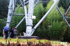
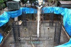
 Deterioration of high-voltage equipment foundations often neglected during maintenance (on photo: Reconstruction of the foundation for power tower)
For convenience a generic grouping of the similar causes, e.g. cracking, chemical reaction, physical reaction, adfreeze and design and construction errors etc. has been adopted. Where possible, an indication of the characteristic feature of the cause has been given.
- Cracking
- Early-age Cracking
- Chemical Reaction
- Physical Reaction
- AdFreeze
- Reinforcement Corrosion
- Muff / Reveal and Cladding Concrete
- Tower / Stub or Grillage Steelwork Corrosion
- Design and Construction Errors
- Audit report of transmission tower (PDF)
1. Cracking
Cracking in concrete is influenced by many factors, which both affect the size and extent of the cracks formed. The nature of the crack, whether active, i.e. increasing in length and width (active cracks) or with insignificant change in length and width (passive cracks) is critical in possible repair options.
Cracking due to the following causes is possible in concrete foundations:
- Early-age cracking which can provide a path for ingress of aggressive agents, eg. chlorides,
- Reactive aggregates,
- Salt crystallisation,
- Sulfate reaction,
- Freeze-thaw,
- Corrosion of reinforcement,
- Ground settlement, and
- Inadequate design and/or poor construction.
2. Early-age Cracking
2.1 Drying Shrinkage
Drying shrinkage cracks occur due to premature drying out of the concrete surface prior to curing, especially when subject to the effects of wind and sun.
2.2 Plastic Settlement
Fresh concrete is a suspension of solids in water; when placed in shuttering – the solids tend to settle. If the settlement of the solids is prevented by obstructions such as the top reinforcement in pad foundations, cracks tend to form as the settling solids fold over the obstructions.
These cracks frequently mirror the reinforcement arrangement.
Go back to the Contents Table ↑
2.3 Plastic Cracking
An associated form of cracking can occur in pad foundations if water is allowed to evaporate before the concrete has been set. The resulting reduction in the volume of the top layer of concrete leads to cracks that can seem very wide, although they usually taper quickly and rarely penetrate the pad, although in certain circumstances they can penetrate up to and beyond the reinforcing.
Go back to the Contents Table ↑
2.4 Thermal cracking
Early-age thermal cracking is caused by restraint to contraction on cooling from a temperature peak, which is associated with the release of the heat of hydration of the binders. Early-age thermal cracking occurs within a few days in thin sections, but it may take several weeks to develop in massive sections.
Figure 1 illustrates the effect of early-age thermal cracking combined with inadequate stub length on a drilled concrete shaft foundation.
Figure 1 – Deterioration of drilled shaft concrete foundation. The cracking of the drilled shaft was due to a combination of the excessive heat of hydration and inadequate stub length.

Go back to the Contents Table ↑
3. Chemical Reaction
3.1 Acid Reaction
Acid reaction is only likely to occur when concrete is in contact with low pH water (pH < 5.5). Acidic water occurs when either organic acids (in peaty areas) or inorganic acids (mining areas) are dissolved in the groundwater.
The acids react with the alkaline compounds in the cement matrix, dissolving and removing them, thereby weakening the concrete paste and increasing its porosity.
3.2 Alkali aggregate reaction (AAR)
Alkali aggregate reaction may occur due to alkali-silica, alkali carbonate or alkali silicate reaction, of which alkali silicate reaction is the commonest. Alkali silicate reaction results from a chemical reaction between alkali hydroxides in the concrete pore solutions and certain types of silica (in the aggregate), which produce an alkali-silica gel. Since the gel can absorb water and swell, generating internal stresses which result in cracking and disruption of the aggregate and cement paste.
For the reaction to occur the following conditions must be satisfied simultaneously:
- a sufficiently strong alkaline pore solution must be present,
- a significant proportion of reactive aggregates lying within the sensitive range,
- sufficient moisture in the concrete.
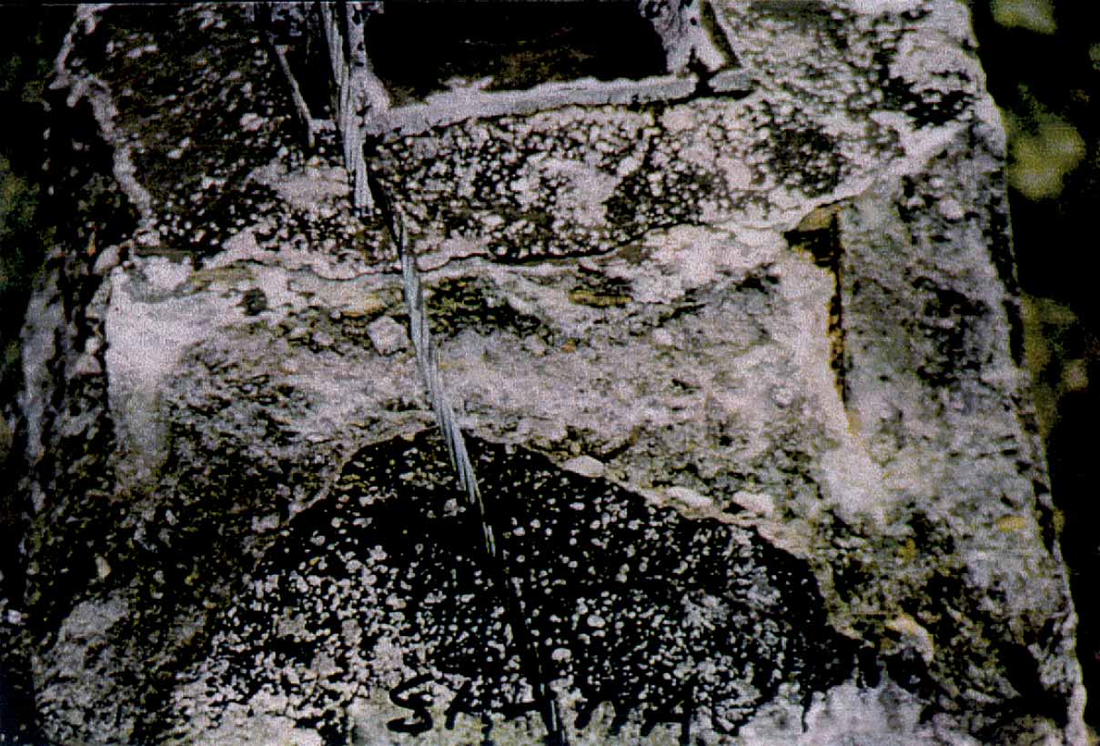
Expansion is not uniform throughout the concrete, resulting in the distinctive map cracking on the surface of the concrete. See Figure 2, which illustrates the effect of AAR on a substation structure foundation.
Figure 2 – Chemical reaction: The effect of Alkali Aggregate Reaction on a substation structure foundation, note distinctive map cracking.

3.3 Carbonation
Carbon dioxide present in the atmosphere dissolves in the concrete pore fluids to produce carbonic acids. The carbonic acid reacts with the cement hydrates to produce calcium carbonate, silica gel, alumina and ferric oxide. Associated with this reaction is a complete loss of alkalinity of the cement paste, with severe consequences for steelwork embedded in the concrete.
Irreversible shrinkage of the concrete may result in surface crazing of the concrete.
3.4 Chloride Reaction
Chloride ions from groundwater, contaminated aggregates or unwashed marine aggregates can react with the cement aluminate paste and the products of the reaction are not expansive, and therefore cracking of the cement paste does not occur.
However, unless crystallisation effects, as described in 3.6 Salt Crystallisation are present, chloride ions can diffuse through the pore solutions of the concrete and thereby initiate corrosion of embedded steelwork.
3.5 Efflorescence
Efflorescence is the deposition of salts on the surface of concrete, due to the flow of water from the interior to the surface. The resulting evaporation on the surface results in the crystallisation of the dissolved salts.
3.6 Salt Crystallisation
Concrete saturated with salt solutions (sulfate and chloride) can suffer from crystallisation damage during periods of alternative wetting and drying. As water evaporates from the pore solutions, the salts concentrate until crystals begin to grow within the pore space.
Since the expansion is impeded, the resulting stresses disrupt the cement paste, causing closely spaced cracks or delaminations parallel to the surface of the concrete.
Suggested training – Physical Asset Management Fundamentals For Electrical Engineers
Physical Asset Management Fundamentals For Electrical Engineers
3.7 Sulfate Reaction
Sulfate salt solutions in the groundwater react with hydrated calcium aluminate in the cement paste. The reaction products (gypsum and calcium trisulphoaluminate), occupy considerably greater volumes than the original compounds. The internal stresses generated lead to disruption of the cement paste.
Indicative levels of water aggressiveness whereby concrete or cement grout will suffer reaction (unless special precautions have been taken) are given in Table 1.
Table 1 – Indicative Levels of Water Aggressiveness
| Agent | Limit Value |
| Acidic water | pH < 5.5 |
| Carbonic acid | < 40 mg/l |
| Ammonium | < 30 mg/l |
| Magnesium | < 1000 mg/l |
| Sulphate | < 200 mg/l |
| Water hardness | > 30 mg CaO /l |
Figures 3, 4 and 5 illustrate the effects of sulfate reaction on concrete.
[hihglight2]Figure 3[/highlight2] – Black coal conveyor system in a thermal power plant
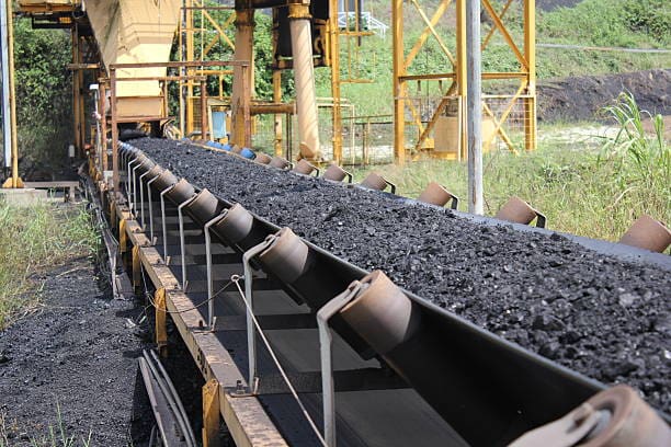
Figure 4 – Idler Pulleys and Structural Support System for Ground Level Reclaim Conveyors. The circular-concrete support piers carry this structural system and are spaced intermittently along both sides of the conveyor.

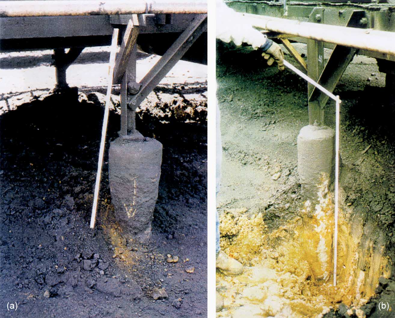
Figure 5 – Deterioration of Circular Concrete Piers Under Sulfate Reaction:
(a) Concrete Reaction on Circular Concrete Pier: Deterioration is more prevalent near the ground surface where the storm drainage in conjunction with the spilled coal creates sulfates as indicated by the necked down condition. Additionally, the deterioration product is washed away exposing the underlying concrete to sulfates.
(b) Sulfate Reaction on Circular-Concrete Support Pier: Excavation along the pier exposed the extent of the deterioration below the ground surface.
Go back to the Contents Table ↑
4. Physical Reaction
4.1 Aggregate Unsoundness
Unsound aggregates ie. those unable to withstand large changes in volume due to freezing and thawing, changes in temperature or alternative wetting and drying, can cause a variety of problems. These problems can vary from local scaling to severe surface cracking and disintegration of the concrete over a considerable depth.
Susceptible aggregates include porous flints or chart, some shales, mining waste, limestones with laminae of expansive clays and other materials containing clay.
4.2 Freeze-thaw
Freeze-thawing of concrete results in the flaking of the concrete surface. This is due to the expansive stresses set up by the water freezing in the concrete pores, thereby causing a series of fine cracks parallel to the surface.
Figure 6 illustrates the effect of cracking on a transmission tower foundation and subsequent reinforcement corrosion, due to severe weathering of the concrete under extreme climatic conditions.
Figure 6 – Physical Reaction: Concrete cracking and reinforcement corrosion due to weathering under severe climatic conditions
Go back to the Contents Table ↑
5. AdFreeze
The adfreeze phenomenon occurs in northern countries where a combination of extremely low temperatures and ground conditions give rise to frost heave problems sufficient to cause the collapse of a tower.
5.1 Permafrost
Permafrost may occur in the form of scattered “islands” ranging in size from a square metre to hectares or larger and in-depth of from less than 3 metres up to one hundred metres or more. There is no fixed pattern to the occurrence of permafrost and it is not unusual to find only part of the ground within a tower site affected by permafrost.
The frozen soils might be silty clays containing ice inclusions as well as ice lenses.
The thawing ground will settle in a non-uniform manner in addition to the change in mechanical properties. The settlement is basically due to the deformation resulting from the consolidation of soils under the action of its own weight. Greater settlements may be anticipated under footings of structures whose design permits the thawing soil to squeeze out from beneath the footing.
The differential ground settlements within a tower site due to consolidation of the thawing soil may vary between 150 mm and 600 to 900 mm under, particularly adverse conditions.
5.2 Frost Forces
The freezing of soils water and the formation of ice lenses results in a swelling of the ground and any foundation members which either bear upon such ground or adhere to it through adfreezing forces may be subjected to high stresses. Direct heave forces acting on the undersides of foundations can generally be minimized or overcome by setting the foundations at a depth below the normal frost penetration.
This, however, does not eliminate the heaving forces transmitted through adfreeze bond to the foundation members which extend through the active layer to the ground surface.
The rate of frost penetration also influences the magnitude of the adfreeze forces. The deterioration of the foundations due to frost heave should be identified and dealt with accordingly.
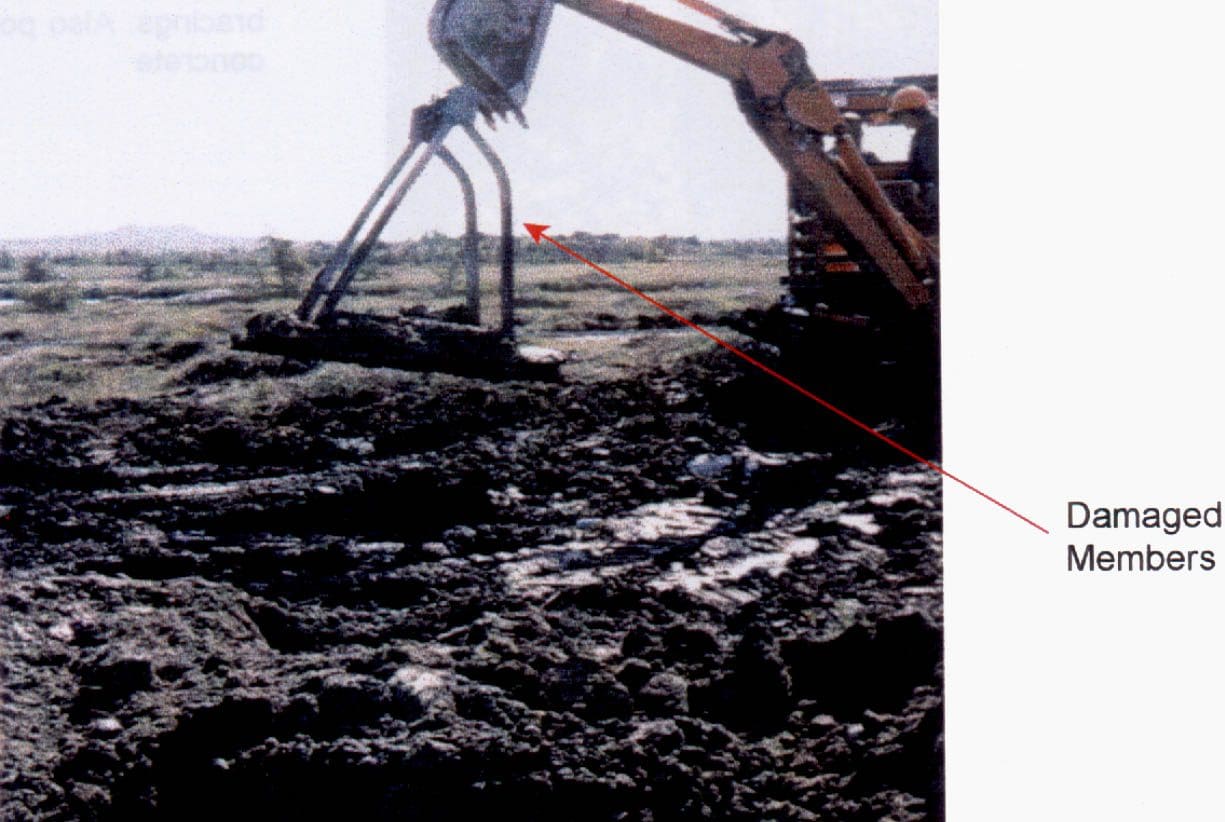
Figure 7 illustrates the effects of frost forces on a guyed tower steel grillage foundation.
Figure 7 – Removal of damaged grillage foundation: Damage caused by frost forces
Go back to the Contents Table ↑
6. Reinforcement Corrosion
Reinforcement corrosion can be caused by the following factors:
- Porous concrete cover,
- Chemical reaction eg. chloride reaction,
- Loss of alkalinity in the concrete and
- Cracking.
Irrespective of the cause, the degree of corrosion will always be exacerbated by the inadequate concrete cover. Reinforcement in concrete is protected by the formation of a thin iron oxide film on the surface, and the resulting passivity is stabilised by the alkalinity of the concrete.
The cracks associated with reinforcement corrosion normally run parallel to the direction of the reinforcement. Oxygen must be present for the process to occur and, therefore, below the zone of air-moisture activity in the soil the rate of corrosion will be low.
Go back to the Contents Table ↑
7. Muff / Reveal and Cladding Concrete
Muff / reveal concrete is used to form a watershed or finish to the top of a concrete foundation particularly the chimney. Cladding concrete is generally added as protection encasing tower steelwork that may either be buried or subjected to flooding, etc.
This secondary concreting is frequently carried out after the main concrete has already cured and hardened, constructed using a weaker mix of concrete that is more porous than the main structural concrete. The bond between the main structural concrete and the finishing concrete is therefore often suspect and cracks form through which moisture and aggressive agents can gain access.
If the finishing concrete is of a poor quality material then again shrinkage cracks can form.
Figure 8, illustrates the corrosion of the bottom tower bracing member within the muff concrete.
Figure 8 – Moisture penetration due to poor application of sealant between concrete and bracings, as well as due to poor quality of muff concrete.
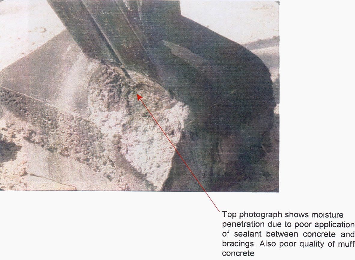
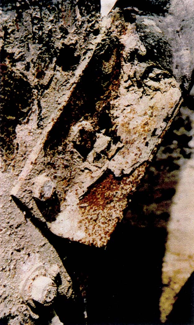
Figure 9 – Severe corrosion of bracing angle due to moisture penetration into the muff concrete
Go back to the Contents Table ↑
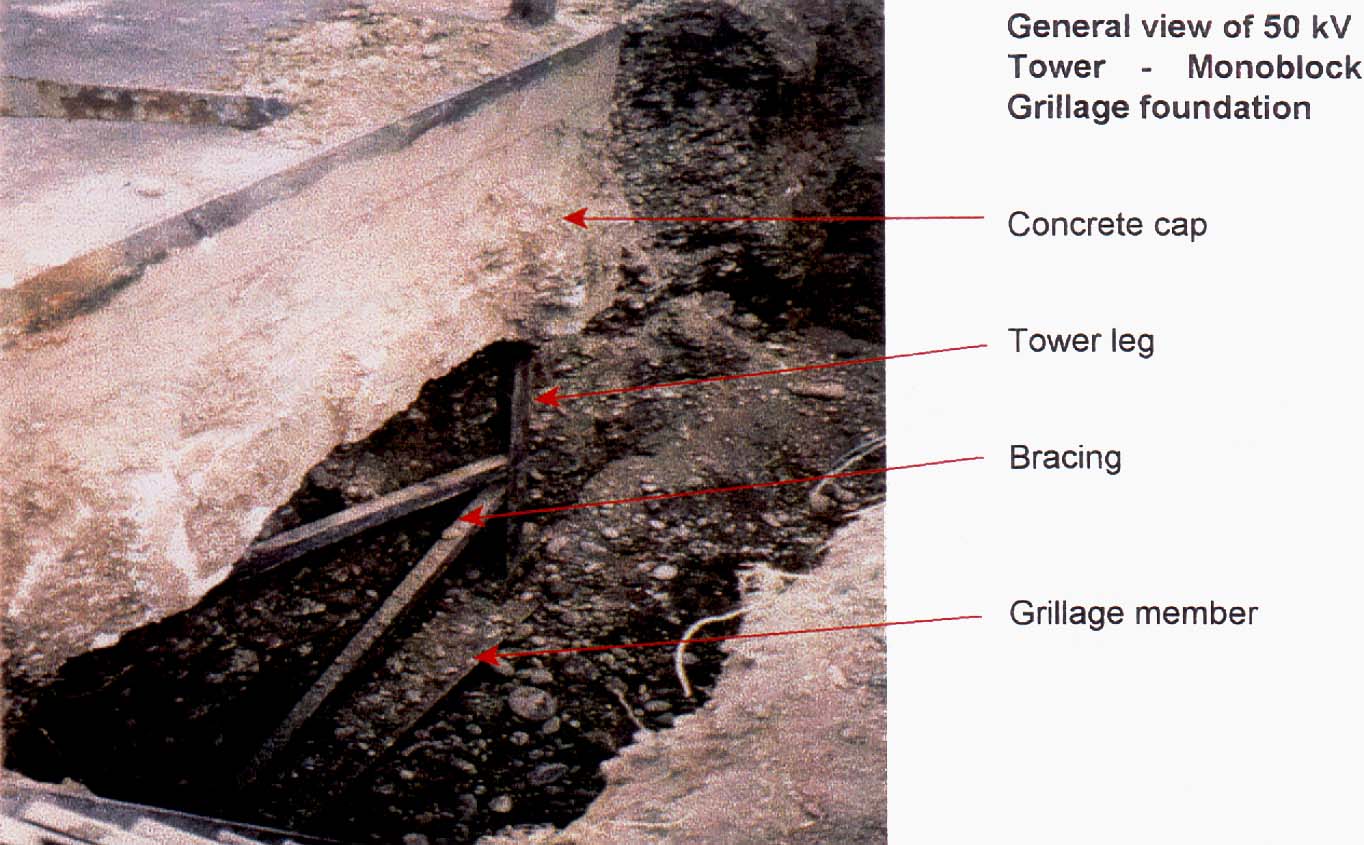
8. Tower / Stub or Grillage Steelwork Corrosion
The corrosion of tower/ stub or grillage steelwork including guy foundation anchor rods and helical screw anchor shafts occurs in a similar manner to that described for reinforcement corrosion. As previously stated oxygen and moisture must be present for corrosion to occur. The exceptions to this rule are the presence of chlorides in groundwater and anaerobic bacterial corrosion in certain soils_
The rate and extent of corrosion will depend on the passivity of the iron oxide film on the surface of the metal for uncoated steel, or the integrity of the surface coating eg. galvanising.
Figure 10, illustrates the effect of corrosion on a steel grillage foundation.
Figure 10 – General view of a 50kV tower – Monoblock grillage foundation corrosion
Go back to the Contents Table ↑
9. Design and Construction Errors
Although design and construction errors potentially cover a wide range of items, it is only those errors that have a long term detrimental effect on the foundation or would prevent the foundation from being refurbished or upgraded, which need to be considered at this time.
9.1 Stub steelwork
Stub steelwork may have inherent faults due to design or installation errors. Possibly the incorrect size and/or a number of cleats and connecting bolts may have been designed, supplied or installed. Alternatively, the incorrect length of the stub may have been supplied and installed. If any such errors are known to have occurred or are suspected, it will be necessary to rectify the mistake when the foundation is due to be refurbished.
Figure 1 illustrates the effect of inadequate stub length on a drilled shaft foundation.
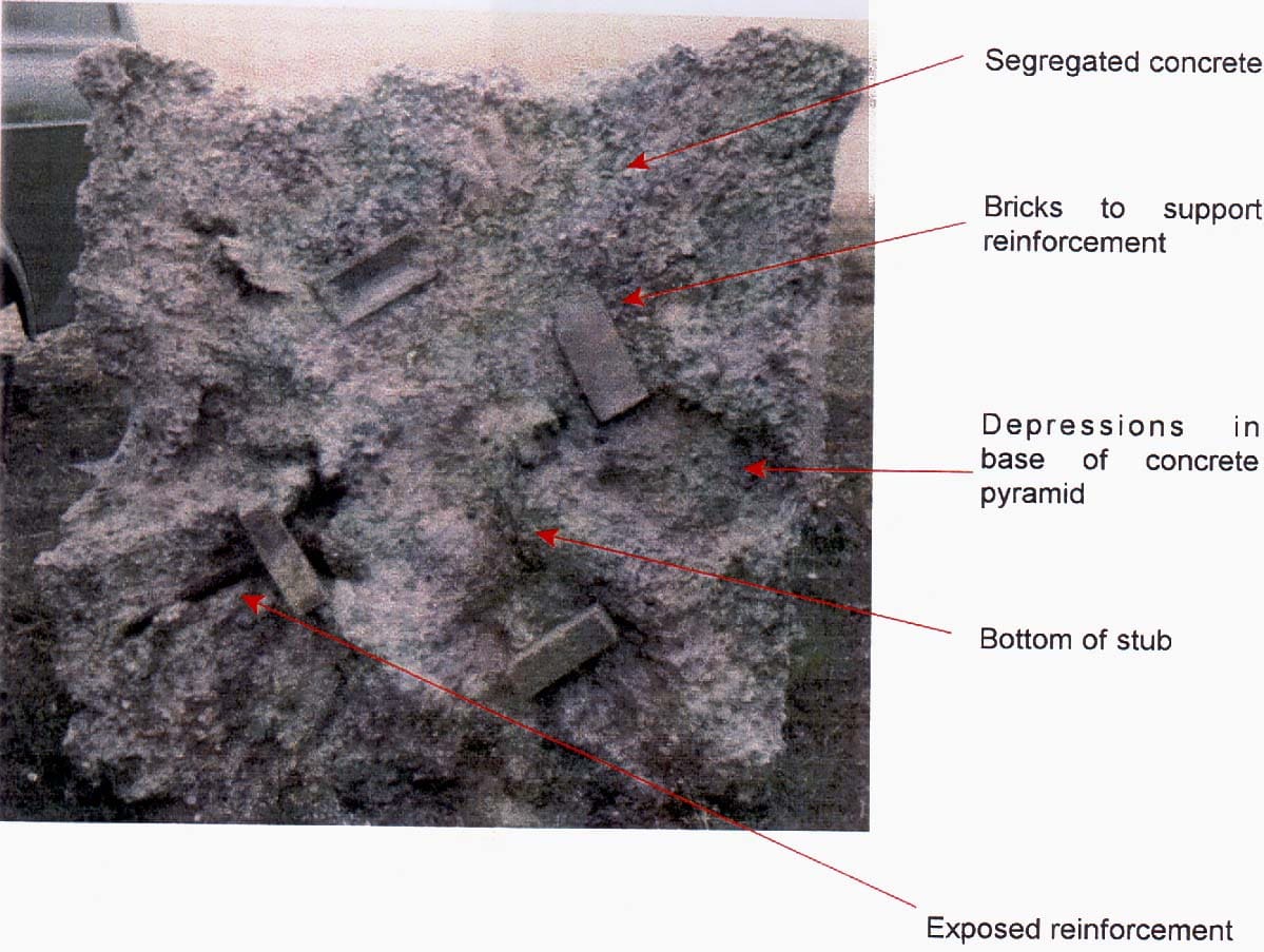
9.2 Construction Faults
Potential problems from construction faults would include early-age cracking, known workmanship problems for similar types of foundations, or potential problems from a study of the construction drawings, e.g. the construction joint at the chimney-pad interface for pad and chimney foundations, ‘necking’ in cast-in-situ concrete piles, omission of the pad undercut assumed in the design, etc.
Figures 11, 12, 13 and 14 illustrate the effects of construction faults on a concrete pyramid and chimney. The faults include poor construction joints in concrete, misalignment of stub and cleats, misalignment of reinforcement, omission of blinding concrete etc.
Alternatively, the potential problems may relate to known or suspect material problems from foundations constructed at the same period, in the same area, or using similar materials, e.g. alkali reactive aggregates.
Figure 11 – Detail of a poor construction joint in a concrete chimney
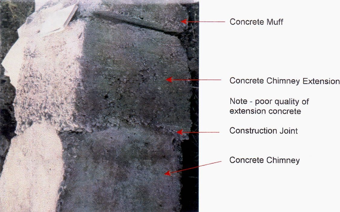
Figure 12 – Misalignment of stub and cleats
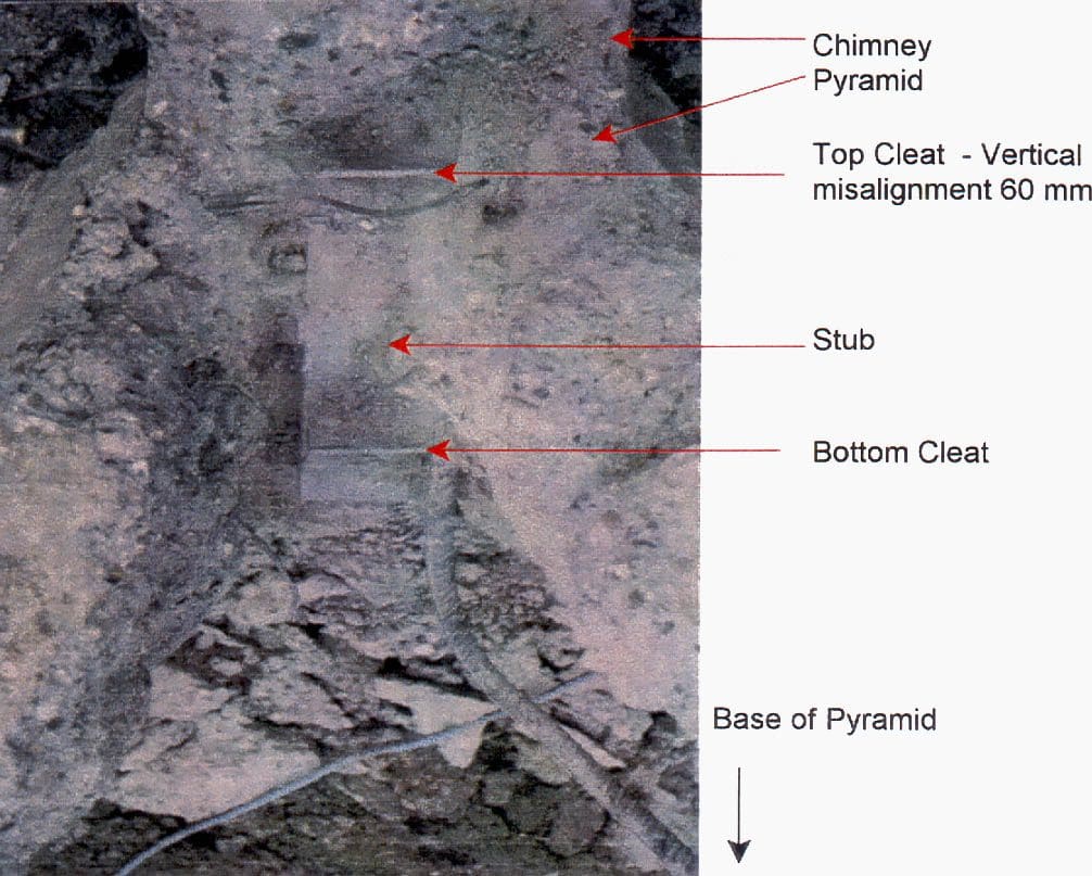
Figure 13 – Misalignment of stub and reinforcing in the concrete chimney
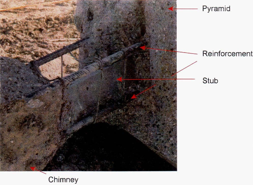
Figure 14 – Construction error
Go back to the Contents Table ↑
10. Audit report of transmission tower (PDF)
Download Report of 4th Pilot audit of Transmission Tower by the audit team of the committee for Audit of Transmission Tower:
Go back to the Contents Table ↑
Source: Refurbishment And Upgrading Of Foundations, Cigre
Related electrical guides & articles


Edvard Csanyi
Hi, I'm an electrical engineer, programmer and founder of EEP - Electrical Engineering Portal. I worked twelve years at Schneider Electric in the position of technical support for low- and medium-voltage projects and the design of busbar trunking systems.I'm highly specialized in the design of LV/MV switchgear and low-voltage, high-power busbar trunking (<6300A) in substations, commercial buildings and industry facilities. I'm also a professional in AutoCAD programming.
Profile: Edvard Csanyi

Thanks for sharing your knowledge.