
Maximum current-carrying capacity
To be clear at the beginning of this article, determining the cross-section of conductors and cables is, for sure, not the most exciting part of electrical design. There are much more challenging and more exciting parts than staring at endless conductor tables. However, this part has to be done professionally the same way as all other parts of a design. So, take your glasses (if you wear one), get some coffee, and let’s start.
 The art of determining the right cross-section of low voltage conductors
The determination of the cross-section of the conductors is based on knowledge of the maximum current-carrying capacity of the wiring system, which is itself determined based on the conductors and their operating conditions. Standard IEC 60364-5-52 determines the current values according to the basic operating principles for installations and safety of people. The main elements are given below.
The table of current-carrying capacities can be used to directly determine the cross-section of the conductors according to:
- Type of conductor
- Reference method (installation method)
- The theoretical current-carrying capacity Iz (Izth)
Izth is calculated by applying all the correction factors (f) to the operating current value (IB). The factors f are determined according to the installation method, grouping, temperature, etc.
IB = Izth× f giving Izth = IB / f
This whole process of determining the right cross-section of low voltage conductors is explained through the following steps.
- Characteristics of the conductors
- Wiring systems: Installation methods
- Groups of circuits
- Ambient temperature
- Risks of explosion
- Parallel conductors
- Global correction factor
- Cross-section of the neutral conductor
1. Characteristics of the conductors
The following information is taken into consideration:
- The type of core: copper or aluminium.
- The type of insulation, which defines the maximum permissible temperature during operation, XLPE or EPR for insulation that can withstand 90 °C and PVC for insulation that can withstand 70 °C
Table 1 – Max. operating temperatures according to the type of insulation
| Type of insulation | Maximum temperature (1) °C |
| Polyvinyl chloride (PVC) | Conductor: 70 |
| Cross-linked polyethylene (XlPE) and ethylene-propylene (EPr) Conductor | Conductor: 90 (1) |
| Mineral (with or without PVC sheath, and accessible) | Sheath: 70 |
| Mineral (without sheath, accessible and not in contact with combustible materials) | Sheath: 105 (2) |
(1) If a conductor operates at a temperature greater than 70°C, it is advisable to check that the equipment connected to this conductor is suitable for the final temperature of the connection.
(2) Higher operating temperatures may be permitted for certain types of insulation, depending on the type of cable, its ends, the environmental conditions and other external influences.
2. Wiring systems: Installation methods
The standard defines a number of installation methods which represent the various installation conditions. In the following tables, they are divided into groups and defined by the letters A to G which determine how to read the table of the current-carrying capacities in conductors (see Anex 1)
There is no explicit provision in the standard on the determination of the cross-section of conductors inside low voltage distribution boards. However standard IEC 60439-1 defines the currents (used for the temperature rise tests) for PVC insulated copper conductors.
Table 2 – Installation group according to the type of cable
| Installation group | Cable type | ||
| Insulated conductors | Single-core cables | Multi-core cables | |
| (A1) in a thermally insulated wall | • | • | |
| (A1) in conduit in a thermally insulated wall | • | • | |
| (A1-A2) in a thermally insulated wall | • | ||
| (B1-B2) in conduit on a wooden wall | • | • | • |
| (C) On a wooden wall | • | • | |
| (C) fixed on a wooden wall | • | • | |
| (D) in ducts in the ground | • | • | |
| (E) in free air | • | ||
| (F) in free air | • | ||
| (G) Spaced in free air | • | ||
For detailed view of each of installation group please refer to Anex 1 below.
3. Groups of circuits
The tables giving the installation methods also refer to specific tables to be used to determine the correction factors connected with the group of circuits and conduits.
Table 3 – Reduction factors for groups of more than one circuit or of more than one multi-core cable to be used with current-carrying capacities

These factors are applicable to uniform groups of cables, equally loaded. Where horizontal clearances between adjacent cables exceeds twice their overall diameter, no reduction factor need be applied.
The same factors are applied to:
- Groups of two or three single-core cables;
- Multi-core cables
If a system consists of both two-core and three-core cables, the total number of cables is taken as the number of circuits, and the corresponding factor is applied to the tables for two loaded conductors for the two-core cables, and to the tables for three loaded conductors for the three-core cables.
For some installations and for other methods not provided for in the above table, it may be appropriate to use factors calculated for specific cases.
Table 4 – Reduction factors for groups of more than one circuit, cables laid directly in the ground installation method D – single-core or multi-core cables

Values given apply to an installation depth of 0,7 m and a soil thermal resistivity of 2,5 Km/W. They are average values for the range of cable sizes and types quoted for tables. The process of averaging, together with rounding off, can result in some cases in errors up to ±10%.
Where more precise values are required they may be calculated by methods given in IEC 60287-2-1.
Table 5 – Reduction factors for groups of more than one circuit, cables laid in ducts in the ground installation method D multi-core cables in single-way ducts


Values given apply to an installation depth of 0,7 m and a soil thermal resistivity of 2,5 Km/W. They are average values for the range of cable sizes and types quoted for tables. The process of averaging, together with rounding off, can result in some cases in errors up to ±10 %.
Where more precise values are required they may be calculated by methods given in IEC 60287.
Table 6 – Reduction factors for groups of more than one multi-core cable to be applied to reference ratings for multi-core cables in free air – method of installation E

(1) Values are given for vertical spacings between trays of 300 mm and at least 20 mm between trays and wall. For closer spacing the factors should be reduced.
(2) Values are given for horizontal spacing between trays of 225 mm with trays mounted back to back. For closer spacing the factors should be reduced
Table 7 – Reduction factors for groups of more than one circuit of single-core cables (1) to be applied to reference rating for one circuit of single-core cables in free air – method of installation F

(1) factors are given for single layers of cables (or trefoil groups) as shown in the table and do not apply when cables are installed in more than one layer touching each other. Values for such installations may be significantly lower and must be determined by an appropriate method.
(2) Values are given for vertical spacings between trays of 300 mm. for closer spacing the factors should be reduced.
(4) Values are given for horizontal spacing between trays of 225 mm with trays mounted back to back and at least 20 mm between the tray and any wall. for closer spacing the factors should be reduced.
(5) for circuits having more than one cable in parallel per phase, each three phase set of conductors should be considered as a circuit for the purpose of this table.
4. Ambient temperature
The ambient temperature has a direct influence on the sizing of the conductors. The temperature to be taken into account is that of the air around the cables (open air installation), and that of the ground for buried cables.
The ambient temperature around cables must not be confused with that taken into account for the protection devices, which is the internal temperature of the distribution swithboard in which these protection devices are installed.
Table 8 – Correction factors for ambient air temperatures other than 30 °C to be applied to the current-carrying capacities for cables in the air (1).
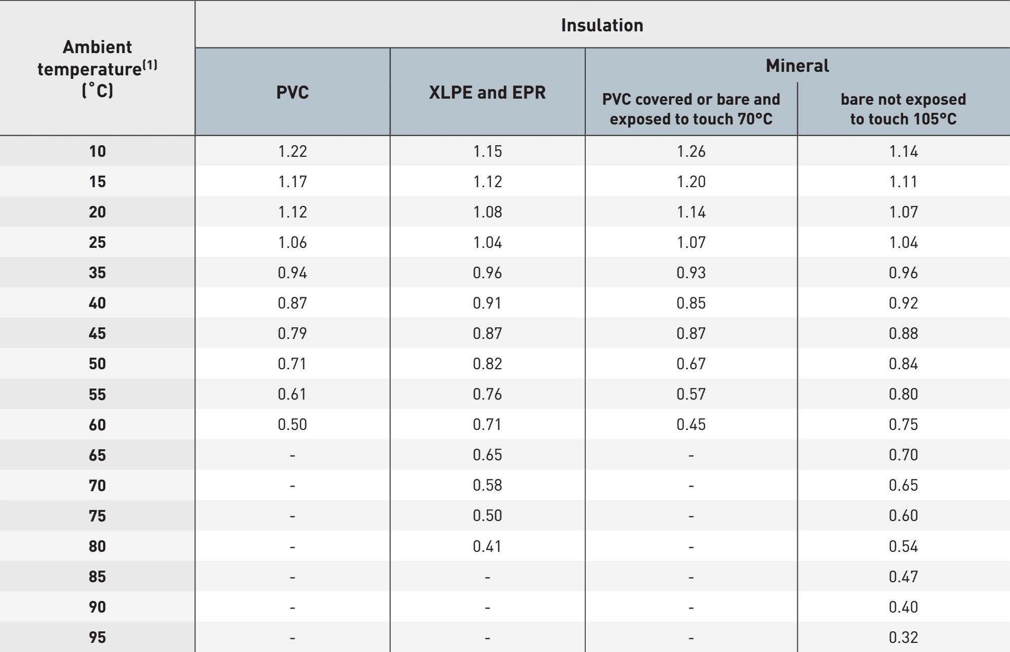
For higher ambient temperatures you should consult manufacturer.
Table 9 – Table correction factors for ambient ground temperatures other than 20°C to be applied to the current-carrying capacities for cables in ducts in the ground

Table 10 – Table correction factor for cables in buried ducts for soil thermal resistivities other than 2,5 K.m/W to be applied to the current-carrying capacities for reference method D

The correction factors given have been averaged over the range of conductor sizes and types of installation considered in tables. The overall accuracy of correction factors is within ±5%. The correction factors are applicable to cables drawn into burried ducts; for cables laid direct in the ground the correction factors for thermal resistivities less than 2,5 K.m/W will be higher.
Where more precise values are required they may be calculated by methods given in IEC 60287. The correction factors are applicable to ducts buried at depths of up to 0,8 m.
5. Risks of explosion
In installations where there is a risk of explosion (presence, processing or storage of materials which are explosive or have a low flash point, including the presence of explosive dust), wiring systems must include appropriate mechanical protection and the current-carrying capacity will be subject to a reduction factor.
The description and installation rules are given in standard IEC 60079.
Interesting reading:
Why substation equipment fails and why it’s wise to think of that much before failure
6. Parallel conductors
As long as the arrangement of the conductors complies with the grouping rules, the current-carrying capacity of the wiring system can be considered as being equal to the sum of the current-carrying capacities of each conductor to which the correction factors connected with the group of conductors are applied.
7. Global correction factor
When all the specific correction factors are known, it is possible to determine the global correction factor (f), which is equal to the product of all the specific factors. The procedure then consists of calculating the theoretical current-carrying capacity Izth of the wiring system:
Izth = IB / f
Knowing Izth then enables reference to be made to the tables for the current-carrying capacities for determining the necessary cross-section.
A tolerance of 5% on the value of iz is generally permitted. for example, an operating current IB of 140 A would lead to the selection of a 35 mm2 cross-section with a current-carrying capacity of 169 A. Applying this tolerance enables a smaller cross-section of 25 mm2 to be chosen, which can then withstand a current of 145 A (138 + 0.5% = 145 A).
Table 11 – Current-carrying capacities in amperes
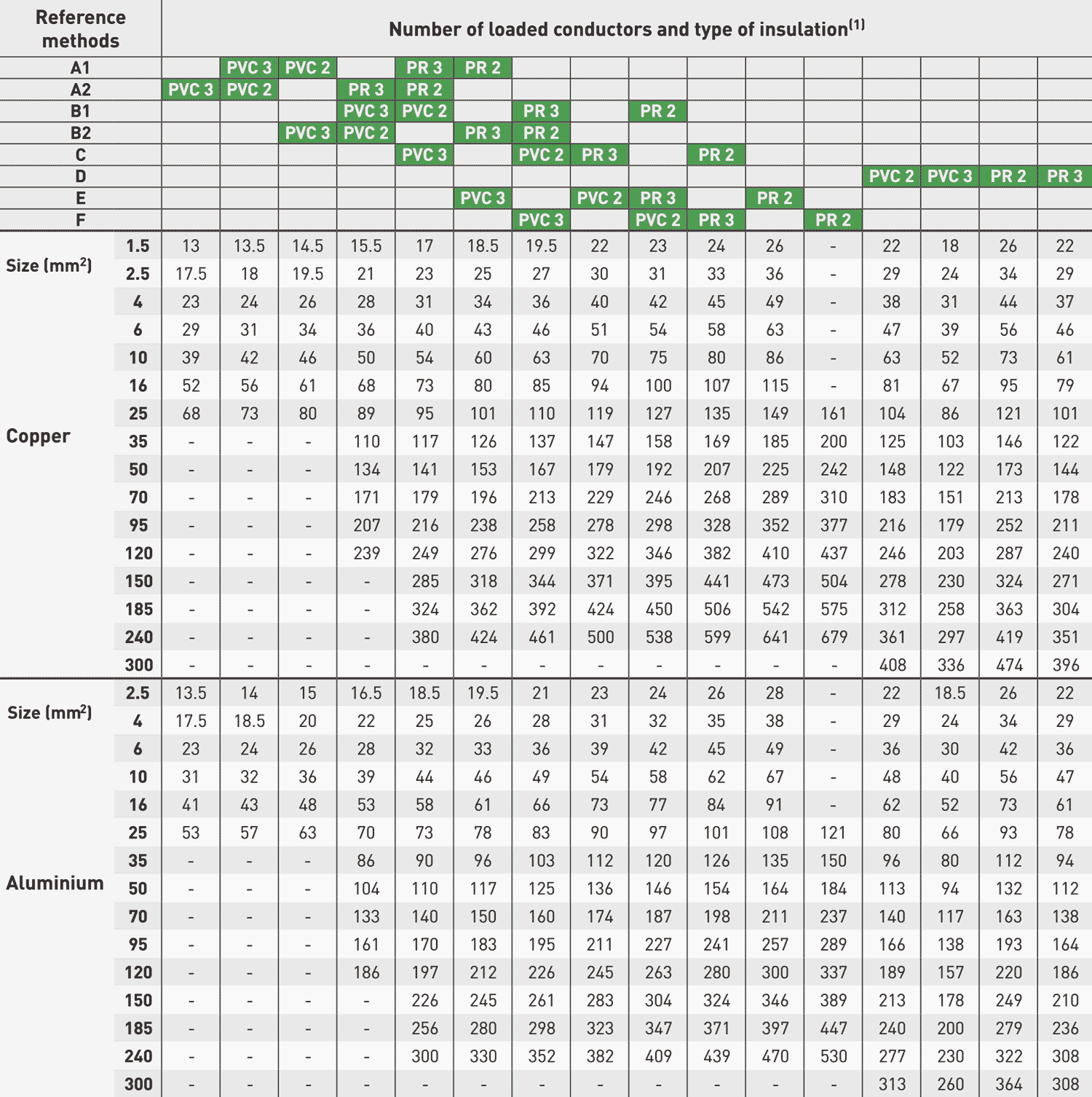
Where (1)
- PVC 2: PVC insulation, 2 loaded conductors
- PVC 3: PVC insulation, 3 loaded conductors
- PR 2: XLPE or EPR insulation, 2 loaded conductors
- PR 3: XLPE or EPR insulation, 3 loaded conductors.
Use PVC 2 or PR 2 for single phase or two-phase circuits and PVC 3 or PR 3 for three-phase circuits.
7.1 Example
Determining a three-phase circuit constituting the link between a main distribution board and a secondary distribution board.
Hypotheses
- The estimation of the loads has enabled the operating current of the conductors to be calculated: IB = 600 A
- The wiring system consists of single-core copper cables with PR insulation
- The conductors are installed touching one another in perforated cable ducting
- Preference is given to install the cables in parallel to limit the unit cross-section to 150 mm2
Solution
Installing single-core cables in a perforated cable tray corresponds to reference method F
If a single conductor per phase is sufficient, no correction need be applied. If two conductors per phase are necessary, a reduction factor of 0.88 must be applied.

The theoretical value Izth will therefore be determined by: Izth = IB/F = 600/0.88 = 682 A i.e. 341 A per conductor.
For a PR 3 conductor in reference method f and a current-carrying capacity of 382 A (value immediately above 341 A) the table gives a cross-section of 120 mm2.
8. Cross-section of the neutral conductor
In principle, the neutral must be the same cross-section as the phase conductor in all single phase circuits. In three-phase circuits with a cross-section greater than 16 mm2 (25 mm2 alumin.), the cross-section of the neutral can be reduced to cross-section/2.
However this reduction is not permitted if:
- The loads are not in practice balanced
- The third harmonic content is greater than 15 %.
Table 15 – Table reduction factors for harmonics currents in 4-core and 5-core cables

8.1 Examples
Application of reduction factors for harmonic currents (IEC 60352-5-52)
Consider a three-phase circuit with a design load of 39 A to be installed using four-core PVC insulated cable clipped to a wall, installation method C. A 6 mm2 cable with copper conductors has a current-carrying capacity of 41 A and hence is suitable if harmonics are not present in the circuit.
If 20 % third harmonic is present, then a reduction factor of 0,86 is applied and the design load becomes: 39/0,86 = 45 A. For this load a 10 mm2 cable is necessary.
If 40 % third harmonic is present, the cable size selection is based on the neutral current which is: 39×0,4×3 = 46,8 A, and a reduction factor of 0,86 is applied, leading to a design load of: 46,8/0,86 = 54,4 A. For this load a 10 mm2 cable is suitable.
If 50% third harmonic is present, the cable size is again selected on the basis of the neutral current, which is: 39×0,5×3 = 58,5 A. In this case the rating factor is 1 and a 16 mm2 cable is required.
All the above cable selections are based on the current-carrying capacity of the cable; voltage drop and other aspects of design have not been considered.
Anex 1 – “Installation groups” according to the type of cable

Sources:
- Legrand


Very interesting write up on electrical power systems
Pls share the info about effect of %THDv on selection of cable cross-section
Cable sizing is a complex activity and different approaches are adopted based on project, geographical location, applicable standards etc. Using the correct tables from the accepted standards is very important. However, there are limitations of the standards too and all practical situations are not addressed in the standards. Sometimes over conservative approach results in oversized cable system. Erring towards undersized cable too is not a safe practice. Years of experience is required to understand cable sizing properly.
MS Excel indeed provides a highly accurate method to store and use data. However, care needs to be exercised to see that data is correctly applied across projects at different geographical locations and also across IEC/NEC world. Customizing worksheets and spending some quality time for spreadsheets is very important. Also any hidden factor which may not be relevant is to be investigated, especially if you are not the the original author. Same holds true for the equations/formulae and the units used.
I don’t know why table 3 were used instead of table 7 for calculating the cables group derating factor in the example. I understood that table 7 should be applied to the current carrying capacity, which do not taken the method of operation into account and table 7 should be applied to the current carrying capacity that take the method of installation into account. So better to use table 7 instead as we already know the method of installation.
From other hand it is more logic to apply the derating factors to the current carrying capacity from the tables rather than the IB. The cable manufacturers have current carrying capacity tables according to the method of installation that means a derating factor has been already used so why we do not continue the same practice.
I want to download articles without premium
I want to download article without premium
Do you have a blog about using DC cables? The proceed is similar i Belice however, if from DC source cable to final load was say 10meters, would you done the length in the calculation due to being a DC circuit?
Excellent your contribution Edvard. Thank you.
Not the first time the metric system has me lost. Great system we just don’t use it in North America. If this is a website designed for Europeans I guess I feel a little left out. Suppose a great way to blog about electrical engineering would be to write in all measurements or at very least use Metric and SAE tables.
I admit AWG system is antiquated but that’s what we still use and I don’t see it changing.
What about short circuit carrying capacity effect in selection of LV cable , by mean suppose if i select a cable sized 120mm2 but as per the short circuit current the per mm current is higher than the acceptable limit then i must modify my selection .
Good reading. Excel spreadsheets are common practice to size cables in offshore projects. They include voltage drop calculations and short circuit withstand capacity in addition to the cable current carrying capacity. Major Class Societies provide temperature-based cable current rating charts, which go into the excel spreadsheets program, along with the derating factors.
Hi Claudio, could you provide me the excel spreadsheets you mention to dimension the wires ??
Thanks!
Hi Claudio. It would be nice if you can share the excel spreadsheets
Hello Edvard,
This is a very good article with an explanation and examples.
I wish you to do much more…articles similar to this.