
AC Generator
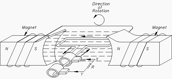
The elementary AC generator (Figure 1) consists of a conductor, or loop of wire in a magnetic field that is produced by an electromagnet. The two ends of the loop are connected to slip rings, and they are in contact with two brushes.
When the loop rotates it cuts magnetic lines of force, first in one direction and then the other.
Development of a Sine-Wave Output
At the instant the loop is in the vertical position (Figure 2, 0°), the coil sides are moving parallel to the field and do not cut magnetic lines of force. In this instant, there is no voltage induced in the loop. As the coil rotates in a counter-clockwise direction, the coil sides will cut the magnetic lines of force in opposite directions.
The induced voltages add in series, making slip ring X (Figure 1) positive (+) and slip ring Y (Figure 1) negative (-). The potential across resistor R will cause a current to flow from Y to X through the resistor. This current will increase until it reaches a maximum value when the coil is horizontal to the magnetic lines of force (Figure 2, 90°).
The horizontal coil is moving perpendicular to the field and is cutting the greatest number of magnetic lines of force.
As the coil continues to turn, the voltage and current induced decrease until they reach zero, where the coil is again in the vertical position (Figure 2, 180°). In the other half revolution, an equal voltage is produced except that the polarity is reversed (Figure 2, 270°, 360°).
The current flow through R is now from X to Y (Figure 1).

The periodic reversal of polarity results in the generation of a voltage, as shown in Figure 2. The rotation of the coil through 360° results in an AC sine wave output
AC Generator – Principles of work (VIDEO)
Cant see this video? Click here to watch it on Youtube.
Conclusion
A simple generator consists of a conductor loop turning in a magnetic field, cutting across the magnetic lines of force. The sine wave output is the result of one side of the generator loop cutting lines of force.
In the first half turn of rotation this produces a positive current and in the second half of rotation produces a negative current. This completes one cycle of AC generation.
Reference: Handbook of electrical science Volume 3 – U.S. Department of Energy





you guys are the best delivering information at the basic understandable level
This article presents a non-practical electric machine, where the coil is in free space. This indeed will result in a sinusoidal induced voltage. In practice, the coil would be embedded in a ferromagnetic material (iron core), thus the magnetic field lines would always be perpendicular to the conductor. This will induce an alternating, but NOT sinusoidal voltage. The waveform will be trapezoid (almost rectangular) in shape. Actually, it takes a lot of effort for machine designers to produce a sinusoidal waveform. The coil distribution has to follow a certain pattern to produce a low harmonic-content sine wave.
Very Nice