
Estimated Study Time: 6 minutes
Main Differences
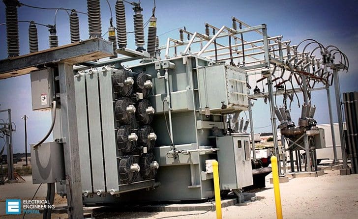
Power transformers are used in transmission network of higher voltages for step-up and step down application (400 kV, 200 kV, 110 kV, 66 kV, 33kV) and are generally rated above 200MVA. On the other hand, distribution transformers are used for lower voltage distribution networks as a means to end user connectivity. (11kV, 6.6 kV, 3.3 kV, 440V, 230V) and are generally rated less than 200 MVA.
Transformer Size / Insulation Level:
Power transformer is used for the transmission purpose at heavy load, high voltage greater than 33 KV & 100% efficiency. It also having a big in size as compare to distribution transformer, it used in generating station and Transmission substation .high insulation level.
The distribution transformer is used for the distribution of electrical energy at low voltage as less than 33KV in industrial purpose and 440v-220v in domestic purpose. It work at low efficiency at 50-70%, small size, easy in installation, having low magnetic losses & it is not always fully loaded.
Iron Losses and Copper Losses
Power Transformers are used in Transmission network so they do not directly connect to the consumers, so load fluctuations are very less. These are loaded fully during 24 hr’s a day, so Cu losses & Fe losses takes place throughout day the specific weight i.e. (iron weight)/(cu weight) is very less.
The average loads are nearer to full loaded or full load and these are designed in such a way that maximum efficiency at full load condition. These are independent of time so in calculating the efficiency only power basis is enough.
Power Transformers are used in Distribution Network so directly connected to the consumer so load fluctuations are very high. these are not loaded fully at all time so iron losses takes place 24hr a day and cu losses takes place based on load cycle. the specific weight is more i.e. (iron weight)/(cu weight).average loads are about only 75% of full load and these are designed in such a way that max efficiency occurs at 75% of full load.
As these are time dependent the all day efficiency is defined in order to calculate the efficiency.
Power transformers are used for transmission as a step up devices so that the I2r loss can be minimized for a given power flow. These transformers are designed to utilize the core to maximum and will operate very much near to the knee point of B-H curve (slightly above the knee point value).This brings down the mass of the core enormously.
Naturally these transformers have the matched iron losses and copper losses at peak load (i.e. the maximum efficiency point where both the losses match).
Distribution transformers obviously cannot be designed like this. Hence the all-day-efficiency comes into picture while designing it. It depends on the typical load cycle for which it has to supply. Definitely Core design will be done to take care of peak load and as well as all-day-efficiency. It is a bargain between these two points.
Power transformer generally operated at full load. Hence, it is designed such that copper losses are minimal. However, a distribution transformer is always online and operated at loads less than full load for most of time. Hence, it is designed such that core losses are minimal.
In Power Transformer the flux density is higher than the distribution transformer.
Watch Video – Power and distribution transformer
Maximum Efficiency
The main difference between power and distribution transformer is distribution transformer is designed for maximum efficiency at 60% to 70% load as normally doesn’t operate at full load all the time. Its load depends on distribution demand. Whereas power transformer is designed for maximum efficiency at 100% load as it always runs at 100% load being near to generating station.
Distribution Transformer is used at the distribution level where voltages tend to be lower .The secondary voltage is almost always the voltage delivered to the end consumer. Because of voltage drop limitations, it is usually not possible to deliver that secondary voltage over great distances.
As a result, most distribution systems tend to involve many ‘clusters’ of loads fed from distribution transformers, and this in turn means that the thermal rating of distribution transformers doesn’t have to be very high to support the loads that they have to serve.
.
Related electrical guides & articles


Jignesh Parmar
Electrical Middle management professional having more than 22 years rich and dynamic experience in Project Execution / Project Management / Designing / Maintenance diversifies from Electrical Power Transmission (400KV/220KV/66KV)- Distribution(11KV/220V) to Lifts-HVAC-Ventilation-Fire Fighting-Fire Alarm-Lifts-CCTV-Stack Parking Works (High Rise Buildings, Townships, Shopping Complex, Commercial Complex, School, Temple).Profile: Jignesh Parmar

Dir sir,
I hope you are doing well.
Thank you for your response, the transformers are not in operation and not purchased yet .
The master plan was conducted by a consultant who decided that our transmission network will consist of six substations , each of them will contain 4 transformers 220/22 kV each of them 70/80MVA ( ONAN – ONAF).
The question is what is the maximum power that can be taken/drawn from the transformers at the peak time taken into consideration the criteria N-1.
The peak time is maximum one hour per day .
Waiting for your response.
Your cooperation is highly appreciated.
B. Regards
Mohammad
Fundamentally the criteria which stipulates ,the power capacity above 200mVA is power transformer and below 200mVA is Distribution transformer is wrong a concept. It means up to 200mVA ,all transformers are distribution transformers?
What should be the ideal ratio of capacity of Distribution transformers to Capacity of Power transformers .Is there any standard in this regard.
Sir …
how the transformer angle design ,how to calculate ? if Dyn11 TRF ,There HV Side angle is 0,240 ,120 its,LV lead 30 dgree to HV , what about LV angle how to calculate ?
Thank u for d information
good
I would like to know the minimum MVA rating of 220kV/11kV step down transformer that can be designed. Can a 220kV/11kV step down transformer of 5MVA rating be designed and what are the design limitations. What are the standard ratings available for the above step down transformer.
The limitation is imposed by Switchgear Vendor for restricting secondary fault current and continuous current.
Wow! Great article, thanks a lot. Calovita
sometimes the receiving end voltage is greater than sending end and this phenomenon is called a Ferranti effect. And this generally occurs in a long transmission line with no load or very low load due to capacitive effect.
THANKS FOR YOUR QUESTION ….
sorry… it will be 287.5v
Receiving EEP news letter
In industries it is common to use transformers redundant for reliability. transformers are normally loaded 50%. Only for the duration of PM or CM, transformers are fully loaded. This is the case with Power transformers for step down in the range of 100MVA as well as distribution transformers of the range of 2MVA. Whats the best way this condition to be conveyed in Requisition for safe, reliable and optimized solution.
At one place in above explanation you have mentioned Power transformer in place of Distribution transformer. So make the correction of it.
Can you tell me about correction as well, where it is? I have to make a project cuz :(
hello Jignesh Parmar
i have adistrubution transformer 3250 kva step down 22kv to 575 volt two secondary
what is the required if i have input only 11 kv ,
i have same output
transformer company (madhya pradesh )
if you give the 11kv to the primary of transformer than output will become 287.5kv.
because output depends upon the primary and secondary number of turns of the transformer.
Hi. I have a question about the correct connection of transformer going to load. We’re using the separate utility transformer which is 44kVA direct to control panel of pump controller and we’re using VFD’s to control the pumps. The question is can I direct connect the secondary line of transfer to main CB(200A) of my control panel or there should be a Breaker before to my Main CB of the control?
Really appreciate of your answer. Thank you.
You can directly feed your Pump Control Panel from Transformer Output provided the distance between the two is less than 15-20 Mtrs.
If the two are located in different rooms you certainly need to add breaker on transformer output..
If the two rooms are adjacent to each other and easily commutable you would not need Breaker on Transformer output Terminals but 15-20 meters limit still stands.
PC Kalra
This is normally the code requirement for safety reasons
For delivering power at 11 Kv ,55 MVA with single run (1cx630 sq.mm, 2d spacing,buried) as space of @1 mtr.trench was available.Now in advance stage power demand increase to 75 MVA and available space for cable route becomes 0.5 mtr width buried cable route(means only trefoil configuration is possible with 1cx 630 sqmm.cable) what to do?
For 132/11 kv transformer what is allowed maximum capacity(KVA) as per latest Indian standard? What are the factor which governs the maximum rating of this transformer?
i feel the corresponding headings are wrongly matched. that is in the place of distribution transformer it was written power transformer. pls check them.
what is practical technical and commercial difference between a DYn11 and YNzn1 for a 220/11kv 25mva transformer.
Why is an electrical jacket cable with multiple insulated conductors inside it,have a twist configuration [not a lot as in data cable, because I know about Near End Cross Talk (NEXT) but still a twist where the insulated conductors are spiralling around the center of the cable under the jacket sheath. Should one undue the spiral where the jacket/sheath is removed and terminate these insulated conductors (straight runs) when attaching them to a bus bar inside a main grid switch gear. Like in the type of switch gear in very large 200ton vessel. Will noise be a result, if these runs are 5ft long (1.5 meters) spiralled.? I wish to know the electrical reason behind this engineering construction configuration method? Thanks.
Educative paper. Has exhausted the topic relevant to both beginners and advanced engineers.
Editor needs to check the language before releasing the paper. In most instances I had to assume what the writer is trying to convey. This is an international platform. Or is it released unedited, on as is basis? Please take note of that. Otherwise I love the platform.
Dear Daniel,
If you understand what the author said means There is no any Language issue.
This is electrical knowledge sharing Site not for testing of language proficiency.
All authors are sharing their knowledge in the cost of their precious time.
Authors are not professional writers and there is no any post of EDITOR.
If you are confident that you are tooooo good in language than try to give your valuable service at any English learning site as a Editor.
Dear sir can you please and please tell me the minimum prize of stepdown transformer far single home use.an electric line of 10000v is pass near my home.I want to get electricity of 210 v fram that line.there is no electricity in my home.can you give me your mobile number sir please
For three-phase transformers with 3 coils made entirely of copper (Cu), the power losses in the whole system will be much lower if the coil is added with iron (Fe).
You can refer to my article
https://fatoro.com/giai-veap-nhung-thac-mac-ve-thiet-bi-may-ap-standa-may-bien-ap Thank you for the article
If a power transformer and distribution transformer are of same duty than whose size is bigger
Which transformer has greater
iron to copper ratio
a power transformer is bigger in size as the rating of power transformer is more than distribution transformer
Dear sir.
good day, can you give me the simple diagram of a 3ph diesel generator connected to 3ph power transformer, and mention the safety device and equipment which are going to used. I hope you can give me the possible solution.
thanks and best regards!
rommel.
Your blog gave me a detailed insight into the topic. It was also very informative and practical.
WHAT IS DIFFERENCE BETWEEN SIMPLE TRANSFORMER AND REAL TRANSFORMER
I don’t get your question actually….. please clarify your question
I didn’t know that power transformers’ average loads are only at about 75% of their full load capacity. Why is that? I’ve heard that certain kinds of transformers are more eco-friendly than others. Is this true? There’s been lots of construction in my neighborhood lately and I’ve noticed transformers being installed and now I’ll be able to have a better idea of what they are and what they do.
Sir, I am a little confused, 420 kV is used in India and 500 kV generation system is used in Pakistan, whether they are same? Please clarify it.
Thanks
Abdul Majid Nasir
I want t o know if I can use 132/11 KV Delta/Star Generator Transformer in place of 132/11 KV Star/Delta Generator Transformer what is happened? If I have no option & I want to use Delta/Star Transformer in place of Star/Delta Transformer what precautions I have to take?
Actually, there is a thumb rule for generation and transmission to use delta winding in low voltage side and star with high voltage side. This thumb rule is totally based on insulation requirement for winding. There is some exception like distribution transformer where star connection is on low voltage side. This type of exception is accepted to supply mix loading.
SIR, MY RESEARCH TOPIC IS A WIND ENERGY I WANT TO MAKE THE STUDY OF THE TRANSFORMER
Helloo every one
I am new to power transformer
Dear sir,
Existing consumer on 11kv/.4v ,1500kw transf.wants to upgrade with 2000kw load and 33/11kv tr. Plus existing infrastructure. Is it worth?please inform about losses,and tech advice ?
With Regard
Thank you
Sir I want to know why the generated voltage in India is restricted to certain level only???????
the generated voltage in india and pakistain has been restricted to a maximum of 33kv, because of the size, maintenance and cost of generators. we can generate volatges more ten 33kv but it needs large size of generators. which cost more as compared to the present generators. its maintenance is difficult to handle. Also due to large size they are difficult to carry from one place to other, but its not a big issue. the main reason is its cost only.
Well…I m interested in rcvg the newsletter.. Kindly send..thumbs up
Correction: In the main heading that says, Iron Losses and Copper Losses. In the second paragraph it would say “Distribution Transformers” instead of “Power Transformers”. Please correct it.
Thanks
Sir,
ours is a 8MW captive power plant with 10MVA distribution transformer 33KV /11KV with some synchronized with grid. The problem is that we ‘ve a disturbing power factor i.e. the of varies very frequently, is there any solution to keep it steady. Please provide a solution if any
Thanking You.
Regards,
Rajshekhar
Hello sir,
As per my knowledge pf is dependent on nonlinear load. There is one probability is that the capacitor banks are not working properly. I am not well known with the other probabilities.
Thank you.
Regards
Siddharth Davda
Yes there is a solution to that you can use condensor’s which on broader sense be called as capacitor hence when you install such instrument with sync. Grid condition it will automatically balance the unstable freq. condition and hence your output PF can be made constant.
sir .i want to known about power transformer .power transformer os a auto transformer ,or 200kv transformer is used to auto transformer
Correction: Power transformers do not work at 100% efficiency, but rather are designed to work at maximum efficiency, at 100% load. Likewise, a distribution transformer is designed (generally), to work at maximum efficiency, at about 75% of full load. Both types of transformer have an excellent efficiency (>97%) – NEVER 50%, unless hardly loaded.
Sir I am very interesting on electrical manufacturing field
Sir,
Please contact on 09881121484 for some important discussions.
Good article. However one Typo error observed. Under Iron and Copper Losses both Power and distribution transformers are given the same heading , viz, ‘Power Transformers’. Please correct when opportunity is available.
Further an article on Selection of transformer Rating for machines with high starting (Pumps Compressors) will also be very informative.
Why Transformer rating is in MW and the induction motor rating is in MVA?
You got it wrong. Transformers and Generators are rated in MVA, Motors are rated in MW and cap banks are rated in MVARs (or respective ‘kilo’ units). The reason why Xfmrs and gen are in MVA because, the type of load is not known. This basically means we don’t know how much MW or MVAR will be loaded on Xfmr or gen. However, a motor has a definite winding and definite power factor and is always inductive nature. Therefore it would be consuming a definite MW. Similarly, a cap bank has definite power factor and is always capacitive in nature. Therefore it would be consuming a definite MVAR. This is undefined for Xfmrs and gen as the load in unknown.
sorry… but your question is totally wrong.
Actually the rating of the transformer is in KVA or MVA and the induction motor rating is in KW or MW. and the reason behind these is that the manufacturers have no idea about the load and power factor is totally depends upon the load so when we multiply power factor with KVA rating of transformer we get the KW rating and in case of induction motor there is no such case of load…..
hence transformer rating is in KVA and the induction motor rating is in KW.
THAKS HOPE YOU LIKE MY ANSWER!!!!!!
Hello Sir, Why Receiving End Voltage is more than the sending end voltage?
Please send appropriate answer for this question….
Sir, receiving end voltage can never be more than sending end voltage.
Sending End Voltage is always higher than Receiving End Voltage due to voltage lost.
if 20 voltage is transmitted, only 18 voltage will get to Receiving End Voltage due to distance, heat, resistivity.
What is advantages and disadvantages 11kv over 33kv? consider (invesment and benefits)?
hi sir – why transmission power transformers(such in powerplant) with same MVA and same condition are very larger than another in different manufacture like mitsubishi or abb ?
very good technical content. Recent Electrical Research paper can be shared on this.
very nice website and shares, thank you so much :)
its great.and fully loaded
it is so much good website
Very nice article indeed , very helpful to show the contrast in power transformer and distribution transformers.
Here is another one i found pretty useful http://electricalstudy.net/working-principle-transformer/
Namesteh Jignesh Parmar sir,
sir plz clear my querry.
If i generate 1 volt ac and with help of a 1:240 transformer, i make it 240 volts then how much current can i take from output terminals. I mean can i glow a bulb of 100 watts with its rated intensity ? I know that some thing is going to be wrng, but i m not able to judge that WHAT ARE THE PARAMETERS, WHICH DONT LET THAT BULB GLOW, are they , the wires of what ? anyone please help
let me first clear you that transformer primary side power and secondary side power is the same….basically transformer just transfers the power from primary to secondary so, the multiplication of V and I are constant that is if the voltage is step up then automatically step down and vis versa. and talking about the bulb it depends upon the rating of the transformer as well as the rating of bulb.
Great job, just to remind that the 2nd paragraph should begin with “Distribution transformers are used in Distribution Network so directly connected to the consumer ” instead of “Power Transformers are used in Distribution Network so directly connected to the consumer ” i guess…
Thanks for the good job
A good and informative article. I appreciate the writer.
BTW, please correct the term Power Transformer in second para under the heading “Iron Losses and Copper Losses”.
Thanks
what is the peculiarity of 315 MVA, 220/132KV, which vector group is YNyno+d1 and YNaod1 power transformer..
kindly send to my email the answer,
Pls send your answer it is very much appreciated
Could you please advise me on distribution class C2 pad mount transformer ? There general specs, feature and application. Can these be used for servicing commericail buildings ( 13.8kV primary, 1250kVA, 600V secondary- for an example).
Thanking you.
There should be no problem to use pad mount transformer class C2 for commercial buildings.
BR