
Estimated Study Time: 30 minutes
Power Distribution Basics
This article will clarify certain frequently misunderstood terms among novice engineers: primary and secondary systems, as well as their equipment and configurations. The transmission and distribution networks of North America are examined as an example. Electricity can be generated from a variety of sources, including fuel (coal, gas, nuclear, oil, etc.), water, wind, and other forms.
 Differences between primary and secondary distribution networks (you MUST know!)
As we already know (or should already know), this process takes place in power plants. The common ratings for three-phase generators used in power plants range from 50 to 1300 MVA.
Terminal voltages of generators can be as low as a few kV or as high as 20 kV, depending on the age and size of the generator. These voltages are constrained by the capabilities of the insulating material and the material itself.
Circuit breakers, surge arresters, and other forms of protection equipment are installed in these substations to ensure the safety of both the GSU transformers and the busses.
1. Transmission & distribution systems
The transmission system performs three primary functions:
- It distributes power from generators to the system,
- It allows for energy exchange between utilities, and
- It provides power to the transmission and distribution systems.
A network of three-phase transmission lines and transmission substations, also known as bulk power substations, comprise the transmission system. Transmission voltages typically range from 230 to 765 kV. Three-phase single-circuit ratings range from 400 MVA at 230 kV to 4000 MVA at 765 kV. In some circumstances, HVDC lines with solid-state converters, as well as back-to-back AC-DC links, are embedded in the transmission system.
Figure 1 depicts the fundamental components of an electric power system.
A sub-transmission line may be tapped in some situations, usually via a circuit breaker, to provide a single-customer distribution load, such as a major industrial plant. Sub-transmission voltages typically range from 69 to 138 kV.
Step-down transformers (distribution substation transformers) are used in distribution substations to reduce sub-transmission voltages to principal distribution voltages in the 2.2 kV to 46 kV range for local distribution. These transformers connect to substation buses via associated circuit breaker and surge arrester protection, which in turn connect to three-phase primary distribution lines known as distribution circuits or feeders via circuit breakers.
Figure 1 – Basic components of an electric power system
Typically, each substation bus serves numerous feeders. Distribution substation ratings typically range from 15 MVA for older installations to 200 MVA or greater for newer installations. Equipment for regulating the primary voltage, such as load tap changers (LTCs) on distribution substation transformers or standalone voltage regulators, may also be found in distribution substations.
Primary distribution feeder ratings for 4.16 kV are typically 4 MVA, 12 MVA for 13.8 kV, 20 MVA for 22.9 kV, and 30 MVA for 34.5 kV feeders. Feeders are typically divided into three-phase sections that are connected by sectionalizing fuses or switches.
Distribution transformers, rated 5 to 5000 kVA, are commonly mounted on utility poles for overhead lines and on ground-level platforms or in vaults for underground cables. Fuse or circuit breakers on the primary and/or secondary sides safeguard distribution transformers against overloads and failures.
Suggested to read – Inside the Modern Digital LV Switchgear: Devices & Communications
Inside the Modern Digital Low Voltage Switchgear: Devices and Communications
Energy flows through secondary mains and service conductors from these transformers to offer single- or three-phase power directly to customer loads (residential, commercial, and light industrial).
Service conductors connect to service panels installed on customers’ properties via meters, which determine kilowatthour consumption for customer billing reasons as well as other data for planning and operation.
The transmission of electric energy from distribution substations to meters at customers’ locations is divided into two parts:
Primary distribution – Which distributes energy in the 2.2 kV to 46 kV range from distribution substations to distribution transformers, where the voltage is stepped down to customer utilization levels.
Secondary distribution – Which distributes energy at customer utilization voltages of 120 to 480 V to meters at customers’ premises.
Suggested reading – Instructions for making specifications and selecting the main components of an HV substation
Instructions for making specifications and selecting the main components of an HV substation
Go back to the Contents Table ↑
2. Primary Distribution Systems
Table 1 depicts common primary distribution voltages in North America. Primary voltages in the ”15 kV class” are common in most utilities. The 2.5 kV and 5 kV primary voltage classes are being phased out in favor of 15 kV primary voltages.
Higher 25 kV to 50 kV classes are employed in some situations in new high-density load zones as well as rural areas with long lines.
The most common is a three-phase, four-wire multi-grounded primary system. Under balanced operating conditions, each phase’s voltage is equal in magnitude but 120 degrees out of phase with the other two phases. In these Y-connected systems, the fourth wire serves as a neutral for the primaries or as a common neutral when both primary and secondaries are present.
Table 1 – Typical Primary Distribution Voltages in US
| Class (kV) | Voltage (kV) |
| 2.5 | 2.4 |
| 5 | 4.16 |
| 8.66 | 7.2 |
| 15 | 12.47 |
| 13.2 | |
| 13.8 | |
| 25 | 22.9 |
| 24.94 | |
| 34.5 | 34.5 |
| 50 | 46 |
On the primary distribution side, the windings of distribution substation transformers are typically Y-connected, with the neutral point grounded and linked to the common neutral wire. The neutral is additionally grounded at regular intervals along the primary, at distribution transformers, and at service entries for customers.
To prevent short circuit currents and increase coordination of protection equipment, distribution substation transformers are sometimes grounded through an impedance (about one ohm).
Overhead primary lines with distribution transformers, fuses, switches, and other equipment installed on poles typically service rural areas with low-density loads. underground cable systems with distribution transformers and switchgear located in subterranean vaults or ground-level cabinets serve high-density loads in urban areas.
Underground residential distribution, particularly single-phase primary servicing residential areas, is also becoming more popular. Underground cable systems are extremely dependable and are typically unaffected by weather.
However, the installation costs of underground distribution are much higher than those of overhead distribution!
Suggested course – Power Engineering Course: Generators, Transformers & Lines
Power Engineering Course: Generators, Transformers and Transmission Lines
Primary distribution includes three fundamental systems:
- Radial systems,
- Loop systems, and
- Primary network systems.
Go back to the Contents Table ↑
2.1 Primary Radial Systems
The primary radial system, seen in Figure 2, is a widely utilized, cost-effective system that is commonly found in low-load-density locations. It is made up of separate three-phase feeder mains (or feeders) that radiate out from a distribution substation, with each feeder serving a specific geographical area.
A three-phase feeder main can range in length from a few miles to 30 miles (48 km). Single-phase laterals (or branches) are typically connected to feeders through fuses, allowing a branch fault to be cleared without halting the feeder.
To balance the loading on the three phases, single-phase laterals are linked to separate phases of the feeder.
Figure 2 – Primary radial system
Overhead feeders can be protected by automatic reclosing devices positioned at the distribution substation, the first overhead pole, or various sites along the feeder to limit the duration of disruptions.
Figure 3 depicts a pole-mount recloser for a 22.9 kV circuit. The vast majority of problems on overhead primaries are transitory, caused by lightning flashover of line insulators, momentary contact of two conductors, instantaneous bird or animal contact, or momentary tree limb contact, according to studies.
During live line maintenance, the reclosing feature is disabled for safety reasons. Reclosing is not employed on primarily underground networks.
Figure 3 – Pole-mount recloser for a three-phase 22.9 kV circuit
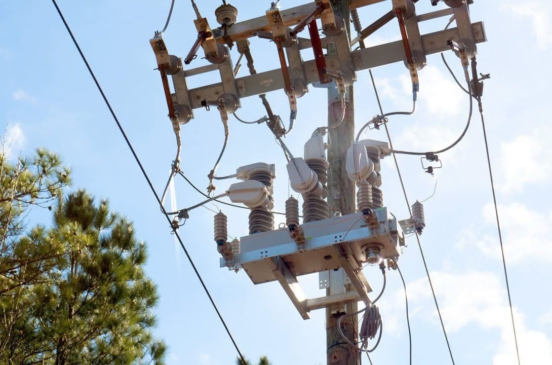
This recloser has a continuous current rating of 800 A and an interrupting current rating of 16 kA. Near the top of the pole is the 22.9 kV feeder. Below the recloser, there are two three-phase 4.16 kV circuits. An antenna positioned beneath the 4.16 kV circuits allows the dispatch center to control the recloser remotely. If the recloser fails to close, a typically open bypass switch placed on the top cross arm can be manually activated.
Sectionalizing fuses are put at predetermined intervals along radial feeders to further limit the duration and degree of customer disruptions. In the event of a fault, one or more fuses blow to isolate the fault, while the upstream portion remains electrified. Furthermore, typically open tie switches to adjacent feeders are included, allowing unfaulted sections of a feeder to be linked to the next feeder during an emergency.
Spare capacity is frequently assigned to feeders to prevent overloads during such circumstances, however there may be sufficient variability between loads on nearby feeders to minimize the need for spare capacity.
A radio-controlled sectionalizing switch on a 22.9 kV circuit is shown in Figure 4.
On primary feeders, shunt capacitor banks, including fixed and switched banks, are used to reduce voltage drop, power losses, and improve power factor. Capacitors are often switched off at night for light loads and on during the day for heavier loads.
Figure 4 – Radio-controlled sectionalizing switch
A pole-mount switching capacitor bank is depicted in Figure 5. There are various computer software available to estimate the number, size, and position of capacitor banks in order to maximize voltage profile, power factor, installation, and operating expenses. Voltage regulators are utilized on primary feeders in some circumstances.
Figure 5 – Pole-mount three-phase 1500 kvar shunt capacitor bank
For important loads, such as hospitals, that cannot tolerate long disruptions, one or more extra, independent feeders along distinct lines may be provided. To prevent the connecting of a good feeder to a defective feeder, switching from the usual feeder to an alternate feeder can be done manually or automatically using circuit breakers and electrical interlocks.
Figure 6 depicts a primary selective system, which is commonly used to supply concentrated loads of more than 300 kVA. In front (upstream) of the distribution transformer, there are two primary feeds with automatic switching.
In the event of a feeder failure, automatic transfer to the other feeder is quick and does not necessitate fault locating prior to transfer.
Figure 6 – Primary selective system
Go back to the Contents Table ↑
2.2 Primary Loop Systems
The primary loop system, as shown in Figure 7 for overhead, is utilized when high service reliability is required. The feeder loops around a load area and returns to the distribution substation, giving two-way feed from the substation.
The size of the feeder conductors, which remain constant throughout the loop, is normally chosen to handle the whole load connected to the loop, including potential load expansion.
Depending on the open/close condition of the reclosers/sectionalizers, power is delivered to a customer via a single path from the distribution substation at any given time. Each circuit breaker in the distribution substation can be connected to a separate bus section and fed by a separate distribution substation transformer.
Figure 7 – Overhead primary loop
Figure 8 depicts a typical underground residential distribution primary loop. The cable size, which remains constant throughout the loop, is chosen to carry the whole load, including potential load increase.
Underground primary feeder faults are significantly less common than overhead primary feeder faults, although they are usually permanent. The time it takes to discover the fault and perform switching to isolate the fault and restore service is the duration of outages caused by primary feeder faults.
Fault locators installed at each distribution substation transformer aid in the reduction of fault locating times.
Figure 8 – Underground primary loop
Go back to the Contents Table ↑
2.3 Primary Network Systems
Although a primary network system, as shown in Figure 9, provides superior service reliability and quality than a radial or loop system, just a few primary networks are still in use in the United States today. They are often found in densely populated downtown districts of large cities.
The core network is made up of a grid of interconnected feeders that are fed by a number of substations. At certain network locations, conventional distribution substations can be replaced by smaller, self-contained unit substations.
Radial primary feeders protected by circuit breakers or fuses can be linked directly at distribution substations or connected into the primary grid.
Figure 9 – Primary network
Go back to the Contents Table ↑
3. Secondary Distribution Systems
Secondary distribution transports electricity at customer use voltages from distribution transformers to meters on the premises of consumers. Table 2 depicts common secondary voltages and uses in North America.
In residential areas, 120/240-V, single-phase, three-wire service is the most common, with 120-V, single-phase connections supplying lighting loads and outlets and 240-V, single-phase connections supplying large household appliances such as electric ranges, clothes dryers, water heaters, and electric space heating.
Table 2 – Typical Secondary Distribution Voltages in US
| Voltage | Number of Phases | Number of Wires | Application |
| 120/240 V | Single-phase | Three | Residential |
| 208Y/120 V | Three-phase | Four | Residential and Commercial |
| 480Y/277 V | Three-phase | Four | Commercial, Industrial, High Rise |
108Y/120-V, three-phase, four-wire service is popular in metropolitan areas supporting high-density residential and commercial loads, where lighting, outlets, and small motor loads are supplied by 120-V, single-phase connections while larger motor loads are supplied by 208-V, three-phase connections.
480Y/277-V, three-phase, four-wire service is popular in locations with very high-density commercial and industrial loads, as well as high-rise structures, with lighting supplied by 277-V, single-phase connections and motor loads supplied by 480-V, three-phase connections.
To serve outlets in various offices, retail establishments, or rooms, separate 120-V radial systems fed by small transformers from the 480-V system are employed.
Figure 10 shows that the first customer, closest to the substation, has the highest voltage, while the last customer, farthest from the substation, has the lowest voltage. According to proper distribution design, the first customer’s voltage should be less than 126 V during light loads and the final customer’s voltage should be greater than 114 V during peak loads, such that all customers remain within 120 V 5% for all normal loading conditions.
Figure 10 – Typical residential customer voltage profile along a radial feeder, assuming no shunt capacitors or voltage regulators along the feeder
Load-tap-changing distribution substation transformers and voltage regulators as well as shunt capacitors are used to maintain customer voltages within ANSI limits.
There are four general types of secondary systems:
- Individual distribution transformer per customer
- Common secondary main
- Secondary network
- Spot network
Go back to the Contents Table ↑
3.1 Individual Distribution Transformer Per Customer
Figure 11 depicts a single distribution transformer with a single service feeding a single customer, which is frequent in rural locations where customer distances are great and long secondary mains are unfeasible.
This approach may also be utilized for a customer who has an abnormally heavy load or who would otherwise have a low-voltage problem with a common secondary main. Although transformer installation and operation costs owing to no-load losses are higher than for other types of secondary systems, secondary mains installation expenditures are avoided.
Figure 11 – Individual distribution transformer supplying single-service secondary
Go back to the Contents Table ↑
3.2 Common Secondary Main
Figure 12 depicts a primary feeder connected to a common secondary main with multiple services to a group of consumers via one or more distribution transformers. This sort of secondary system takes advantage of customer demand variability, allowing a smaller capacity of the transformer serving a group compared to the sum of individual transformer capacities for each customer in the group.
Furthermore, the big transformer providing a group can manage motor starting currents and other sudden load changes without causing significant voltage dips.
In some cases, fuses are installed along a continuous secondary main, which results in banking of distribution transformers, also called banked secondaries.
Figure 12 – Common secondary main
Go back to the Contents Table ↑
3.3 Secondary Network
Figure 13 depicts a secondary network or secondary grid that could be utilized to service high-density load zones in city centers where the highest level of reliability is required and revenues cover grid expenditures.
The underground secondary network is fed at the same time by two or more primary feeders via network transformers. Most networks are fed by three or more primary feeders with spare capacity transformers, allowing the network to operate with two feeders out of service.
Secondary grids operate at either 208Y/120 or 480Y/277-V in the United States. Commonly used secondary cable sizes range from 4/0 to 500 kcmil AWG.
Some of the secondary networks in New York City are fed by as many as 24 primary feeders operating in parallel.
Network transformers are protected by network protectors between the transformers and secondary mains. A network protector is an electrically operated low-voltage air circuit breaker with relays and auxiliary devices that automatically opens to disconnect the transformer from the network when the transformer or the primary feeder is faulted, or when there is a power flow reversal.
The network protector also has the ability to close automatically when a feeder is energized. Fuses may also be used for backup of network protectors.
Figure 13 – Secondary network
In many cases, especially on 208Y/120-V secondary networks, main protection of secondary cables has come from the ability of the cable system to ‘‘burn clear’’ with no fuse or other protective device. However, in many instances for 480Y/277-V secondary networks, this practice was not able to successfully burn clear, resulting in fires and considerable damage. As a solution, special fuses called cable limiters are commonly used at tie points in the secondary network to isolate faulted secondary cables.
Cable limiters, which are designed with restricted sections of copper which act like a fuse, do not limit the magnitude of fault current like current limiting fuses. In high short circuit locations on the secondary network, current limiting fuses may be used instead of cable limiters.
Also, each network is designed to share the load equally among transformers and to handle large motor starting and other abrupt load changes without severe voltage drops.
Suggested guide – Design guide for upgrading existing secondary substations to be smart and intelligent
Design guide for upgrading existing secondary substations to be smart and intelligent
Go back to the Contents Table ↑
3.4 Spot Network
Figure 14 shows a spot network consisting of a secondary network supplying a single, concentrated load such as a high-rise building or shopping center, where a high degree of reliability is required. The secondary spot network bus is supplied simultaneously by two or more primary feeders through network transformers.
In some cases, a spot network load as large as 25 MVA may be fed by up to six primary feeders. Most all spot networks in the North America operate at a 480Y/277-V secondary voltage.
Network protectors are used to automatically disconnect transformers from the spot network bus for transformer/feeder faults or for power-flow reversal, and cable limiters or fuses are used to protect against overloads and faults on secondary cables. Scheduled or forced outages of primary feeders occur without customer interruption or involvement.
Spot networks also provide a very compact and reliable arrangement of components.
Figure 14 – Secondary spot network
Go back to the Contents Table ↑
Sources:
- Power System Analysis And Design By J. Duncan Glover, Mulukutla S. Sarma And Thomas J. Overbye
- Industrial Power Systems Handbook by Donald Beeman
Related electrical guides & articles


Edvard Csanyi
Hi, I'm an electrical engineer, programmer and founder of EEP - Electrical Engineering Portal. I worked twelve years at Schneider Electric in the position of technical support for low- and medium-voltage projects and the design of busbar trunking systems.I'm highly specialized in the design of LV/MV switchgear and low-voltage, high-power busbar trunking (<6300A) in substations, commercial buildings and industry facilities. I'm also a professional in AutoCAD programming.
Profile: Edvard Csanyi

I think and find that the information available when defining or pointing out what a primary system is and what a secondary system is in Electrical Power System Engineering is still not very clear. It appears that these two areas are not clearly explained. Would it be possible to have these two areas (primary, secondary) to be clearly defined and pointed out so that this is very clear and does not remain rather blurred as I find at many situations where this is written about, e.g. Primary Design Engineer, Secondary Design Engineer. Can someone please explain what is the difference between these two?
Kindly send us troubleshooting shooting updates.