Two Cases Of Feeder Protection
On transformer feeders, the transformer and line or cable are connected in series and form a unit. In this manner, one CB can be saved. On feeders with tee-offs, transformers along the feeder are directly connected. In this case, a substation is saved. In both cases the protection is faced with particular difficulties. The Siemens SIPROTEC product range will be used for this purpose.

Let’s have discussion on these two cases:
Protection of transformer feeders
The differential protection for this application must include the special features required in transformer differential protection: ratio and vector group adaptation, as well as in-rush blocking and stabilizing against over-fluxing.
In addition the protected object must be allowed to extend over larger distances, which means that the measured value transferral must have the properties of a feeder differential protection.
The normal feeder differential protection was however also applied. For this purpose the CTs at one end were connected in delta to provide the vector group adaptation. The inrush blocking was provided at both ends by means of supplementary relays.


With numerical technology, a relay is now available which includes the properties of a transformer and feeder differential protection in a single unit (7SD84). Figure 1 states an application example.
Optionally, a differential relay with integrated distance zones (7SL86) could be chosen. In this case under-reaching zones would be graded into the transformer from both sides. This would provide fast protection even when the signal transmission fails, and also allow a rough discrimination between primary and secondary winding faults.
Voltage transformers would however be needed at the side(s) where the 21 function is applied.
In the example overcurrent protection (50/51) is provided at both sides as back-up protection.
Differential protection for feeders with tee-offs (tapped lines)
Direct tees off the feeder without switchgear are common in distribution networks (132 kV and below). In many cases several tees are present. These may be pure consumers (load) as well as back-feeds (distributed generation). The connection may be applied with or without CB.
Earthing of the transformer star point on the feeder side is not always the same. In earthed systems the star point of the transformer at the tap may be isolated or effectively earthed. The protection concept must be individually adapted to the conditions of the application at hand.
The maximum short-circuit current during a fault on the secondary side of a tap transformer must be considered in any event. If signal communication is available, the differential protection on the feeder may be blocked during critical conditions if the protection on the secondary side of a transformer tap picks up.
Alternatively a non-directional distance protection zone may be applied as release criterion for the feeder differential protection. This zone must cover 100% of the feeder (setting 120% ZL), may however not reach through the tap transformer. Suitable setting can be found when the rating of the tap transformers is not very large and when the feeder is not too long as shown in the following example.


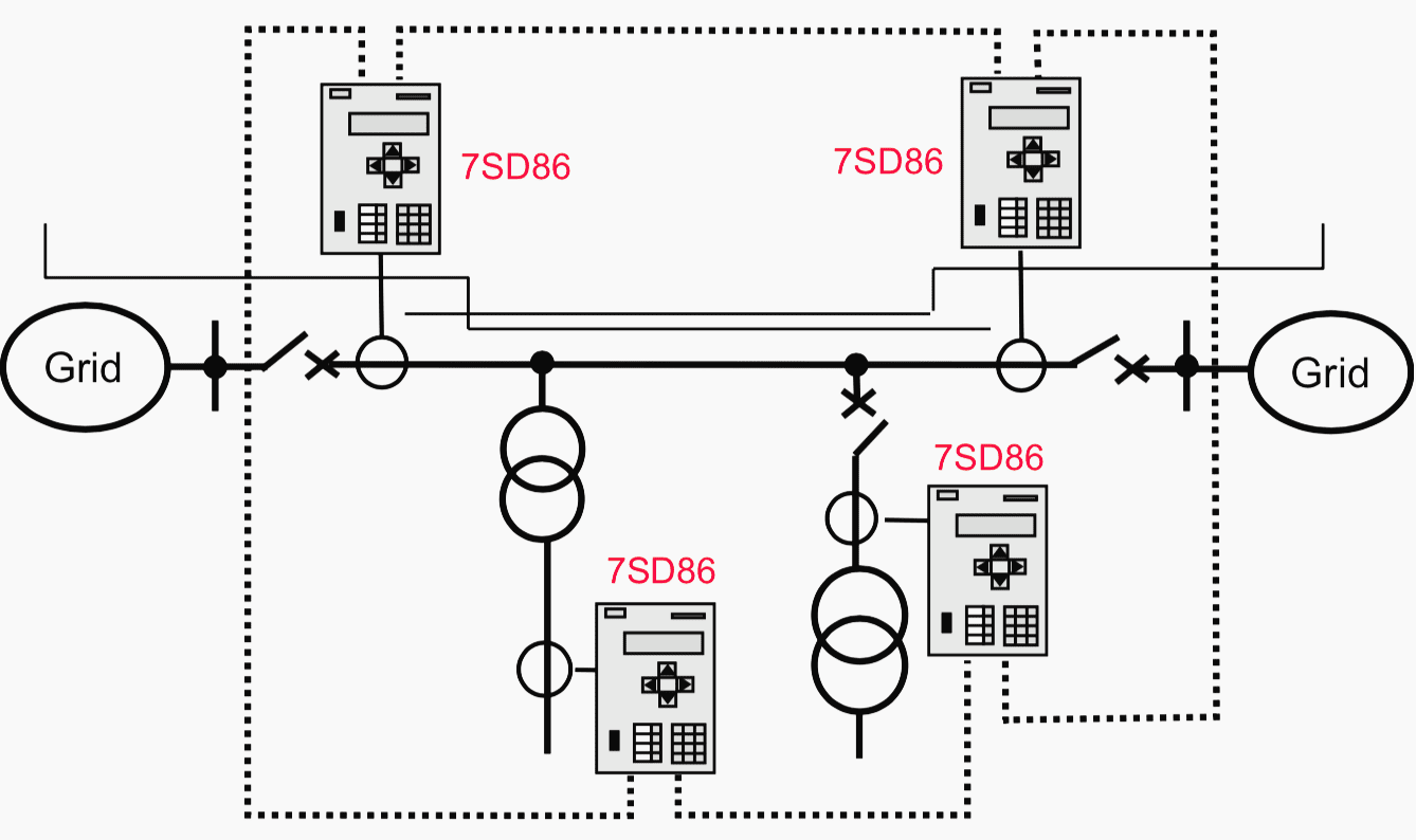
With the numerical protection the feeder with tee-offs can be optimally protected if broad band communication (FO or directional radio) is available. The numerical feeder differential protection 7SD52/86/87 for up to 6 line ends (that is 4 tee-offs are permitted) can be applied (Figure 2 above).
Transformers may also be included in the protected object (left-hand side transformer in Figure 2 above), as all the above mentioned functions of the transformer protection are integrated in the relay.
If a distance protection zone release is applied as described above, the integrated distance protection (option in 7SL86) may be used for this purpose.
Example
Setting of the numerical pilot protection on a line with tee-offs.
Given:
- HV feeder 110 kV,
- l = 27 m,
- XL = 0.4 Ω/km
Data of the system in-feed and the tee-offs according to Figure 3:


Wanted (2 Questions)
- How high must the pick-up threshold of the differential protection be set?
- Can increased pick-up sensitivity be achieved by applying a distance zone release?
Solution
The short-circuit impedances were calculated and are entered in Figure 3.
The largest error current (differential current) for the differential protection results during a short circuit behind the 20 MVA transformer:


The pick-up threshold of the differential protection should therefore be set to IDiff ≥ 1.3·957 = 1244 A, providing a security margin of 30%. This setting would then correspond to three times the CT nominal current.
A distance protection zone with 20% overreach would have to be set to:
ZOR = 1.2·0.4 Ω/km · 27 km = 13 Ω
For the setting of the distance zone, the inrush current of the transformer must also be considered, when the feeder is energised from one end.
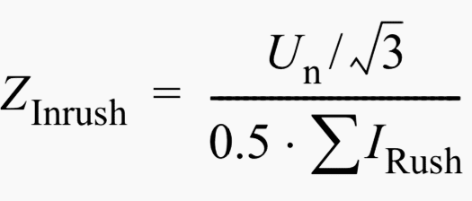
The distance protection then measures the impedance:


For this calculation it was assumed that the numerical protection only evaluates the fundamental and that the fundamental component of the inrush current is not greater than 50%.
Furthermore it is assumed that for the transformer size of this example, the rush currents do not exceed the value equal to 5 times nominal current so that the following approximation can be made:


The measured impedance is therefore far enough outside the intended setting of 50 Ω.
The overreaching zone in this example is therefore perfectly suited for release of the feeder differential protection. The pick-up threshold could be reduced to approximately half CT nominal current. In other words 200 A could be set.
IMPORTANT NOTES:
With the conventional protection technology, the direction measurement for close-in faults was not obtainable with absolute security. Voltage memory was relatively expensive and was only applied at the EHV level.
The differential protection was therefore superior for providing 100% protection coverage of the feeder when compared to the directional comparison principle.
With the modern distance protection the direction measurement is secure due to the digital voltage memory. A directional comparison protection is therefore comparable with the differential protection in terms of selectivity, especially as the direction comparison can now also be done on a per-phase basis (SIPROTEC relay 7SA6).
A degree of restriction in terms of selectivity for the distance protection only results in the event of multiple or sequential faults, which are very rare.
For the example described above, it would therefore have to be considered whether a distance protection with directional comparison would not be preferable to achieve a simpler solution.
The particular advantage of differential protection is its independence of voltage transformers. The release by a distance zone should in any event not be applied instead of, but in parallel to a current release criterion, so that only the pick-up sensitivity for small current faults is increased.
REFERENCE: // Numerical Differential Protection – Principles and Applications by Gerhard Ziegler (Purchase hardocopy from Amazon)


is the Protection of transformer feeders applied any where in electrical distribution utilities?, please clarify.
This is a very good site for Electrical Engineers to improve the technical knowledge and to clear the doubts regarding technical issues. contents are very informative and useful.
Thanks a lot.
Stephen.